
A solar string configuration is the way individual solar panels are wired together, either in series, in parallel, or in a mix of both, to produce a voltage and current that a specific inverter can accept safely. Get this wrong and you’re not looking at a minor inefficiency. You’re looking at an inverter that won’t switch on in the morning, or worse, one that trips out and fails the moment temperatures drop below freezing.
Three checks decide whether any string design actually works. First, the coldest realistic Voc (open circuit voltage) on your roof must sit below the inverter’s maximum DC input voltage, because voltage rises as panels get colder. Second, the hottest realistic Vmp (voltage at maximum power) must sit above the inverter’s minimum MPPT (maximum power point tracking) voltage, because voltage falls as panels heat up. Third, the string and combined array current must stay inside the limits of the inverter’s input, the fuses, and every connector in the circuit.
The practical shortcut is this: wire panels in series to push voltage up, wire them in parallel to push current up, and use series-parallel when you need to balance both across a bigger array. But that shortcut only works once you’ve proven the design against the three checks above, using real numbers from the module and inverter datasheets, not marketing wattage.
Key Takeaways
A safe, efficient solar string configuration depends on matching cold-temperature Voc, hot-temperature Vmp, and combined current against the exact limits stated on the inverter and module datasheets.
| Point | Details |
|---|---|
| Check cold Voc first | Confirm the coldest realistic Voc per string stays below the inverter’s maximum DC input voltage. |
| Check hot Vmp second | Confirm the hottest realistic Vmp per string stays above the inverter’s MPPT minimum voltage. |
| Size for current, not just voltage | Sum Imp across parallel strings per MPPT input and check against the inverter’s rated maximum current. |
| Map shade before wiring | Separate differing roof planes onto their own MPPTs or use module-level electronics where shading varies. |
| Label and document everything | Record string counts, datasheet references, and isolator locations for the homeowner’s handover file. |
Where to check the numbers yourself
Keep a short reference list alongside the installation paperwork. The energy.gov solar design basics page covers the underlying electrical principles behind series and parallel wiring in plain terms. The LBL PVTools string length calculator lets you test a specific module and inverter combination against cold-temperature Voc corrections without doing the arithmetic by hand. Aurora Solar’s wiring basics guide and NerdVolt’s series and parallel wiring guide both walk through the practical checklist in more depth, and The Green Watt’s wiring guide is useful for wire-gauge rules of thumb. If you want background on how module efficiency figures feed into the Voc and Vmp numbers you’ll be working with, HomeEnergyModel’s explainer on solar panel efficiency is worth ten minutes before you start pulling datasheets.
An installer’s honest take on conservative stringing
Every experienced installer ends up conservative about Tmin and Voc margins, and it’s not caution for its own sake. It’s because the failure mode for an undersized margin isn’t a slightly lower yield, it’s an inverter that shuts itself down on the one frosty morning of the year, or worse, exceeds its input rating and damages internal components. I’d rather lose a fraction of a percent of theoretical output by leaving headroom than field a callout in January because a string was sized against a mild average instead of the coldest morning the roof will actually see.
The same logic applies to MPPT allocation on complex roofs. Forcing two differently-angled strings onto one MPPT to save the cost of an extra input, or skipping optimisers on a roof with genuine shading, always looks fine on the commissioning day when the sun is directly overhead and every panel is performing identically. It stops looking fine six weeks later when a chimney shadow starts clipping one corner of the array every afternoon. Separate MPPTs and module-level electronics cost more upfront. They also stop that shading problem from ever becoming the homeowner’s problem.
Table of Contents
- What is a solar string configuration made up of, electrically?
- How do series, parallel and series-parallel wiring differ?
- How do you calculate panels per string?
- Which wiring components sit between the panels and the inverter?
- How does shading affect string performance?
- Two worked examples: single-plane and mixed-plane roofs
- What should you check before switching the system on?
- How do installers actually plan string routing on a real roof?
- What are the safety and regulatory basics to know?
- Why does Smarthometechnical favour conservative string margins?
- Frequently asked questions
- Sources
What is a solar string configuration made up of, electrically?
Before any of the sizing maths makes sense, you need six terms fixed in your head. Miss one and the whole calculation falls over, because each check in the BLUF above depends on a specific pairing of these values.
- Voc (open circuit voltage): the voltage a panel produces with no load connected. This is the figure that determines your cold weather safety margin, since Voc climbs as the panel cools.
- Vmp (voltage at maximum power): the voltage a panel actually operates at when delivering its rated output. This is what you check against the inverter’s MPPT minimum on a hot afternoon.
- Isc (short circuit current): the maximum current a panel can produce, used for fuse and conductor sizing.
- Imp (current at maximum power): the operating current under normal load, used to calculate combined current in parallel strings.
- Temperature coefficient of Voc: usually expressed as a percentage per degree Celsius (something like negative 0.29%/°C), this tells you how much voltage changes for every degree away from the standard 25°C test condition.
- MPPT range and maximum DC input: the voltage window an inverter’s power point tracker can work within, and the absolute ceiling it must never see.
This is exactly why datasheets matter more than brand loyalty. A SolarEdge HD-Wave inverter has a different maximum input voltage and MPPT window to an SMA Sunny Boy, a Fronius Primo, an Enphase microinverter, or a GivEnergy hybrid unit, and every one of those manufacturers publishes the exact figures you need on the datasheet, not the box. Even the small stuff counts: MC4 connectors, the near-universal plug-and-socket fitting joining most panels together, carry their own current rating, and that rating becomes the ceiling on how many strings you can safely combine before a proper combiner box takes over.
How do series, parallel and series-parallel wiring differ?
Series wiring connects the positive terminal of one panel to the negative terminal of the next, all the way down the string. Voltages add up while current stays roughly the same as a single panel. Four 400W panels in series with a Vmp of 34V each give you a string voltage around 136V, at the same current one panel produces alone.
Parallel wiring connects all the positive terminals together and all the negative terminals together. Current adds up, voltage stays close to that of a single panel. The same four panels in parallel would give roughly 34V but four times the current, which is rarely useful on a domestic roof unless you’re feeding a low-voltage battery system directly.
Series-parallel combines both: you build two or more identical series strings, then wire those strings together in parallel at a combiner or at the inverter’s input terminals. This is how most residential and small commercial arrays end up wired, because it lets you hit a workable string voltage while spreading the total panel count across more roof area than a single string could handle.
| Configuration | Voltage behaviour | Current behaviour | Shade tolerance | Typical use case |
|---|---|---|---|---|
| Series | Adds across all modules | Stays at single-module level | Poor. One shaded panel drags the whole string down | Single-plane roofs, higher-voltage string inverters |
| Parallel | Stays at single-module level | Adds across all modules | Better isolation between strings, but each string still suffers internally | Low-voltage battery charging, small off-grid setups |
| Series-parallel | Adds within each string | Adds across strings | Depends on grouping. Separate MPPTs help isolate shaded areas | Most residential arrays, mixed-orientation roofs |
Keep every module in a given string identical in wattage and electrical spec. Mixing a 370W panel with a 410W panel in the same series string means the weaker panel sets the ceiling for the entire string’s current output. Where a roof has two distinct planes, east and west-facing for instance, wire each plane as its own string on its own MPPT input rather than forcing them together. A two-panel test string wired positive-to-negative with MC4 leads run to a small combiner box, then out to the inverter, is the simplest version of this pattern and it scales cleanly to four, six, or ten panels per string.
How do you calculate panels per string?
Sizing a string correctly comes down to four pieces of paperwork and two temperature-adjusted sums. Skip the paperwork and you’re guessing.
- Pull the module datasheet. You need Voc, Vmp, Isc, Imp, and the temperature coefficient of Voc (usually shown as %/°C).
- Pull the inverter or MPPT datasheet. You need the maximum DC input voltage, the MPPT operating range (minimum and maximum), and the maximum input current per MPPT channel.
- Set your Tmin and Tmax assumptions. Use the coldest and hottest realistic ambient temperatures for the installation site, not the mildest week of the year. Many installers add a margin below the local record low to stay safe.
- Calculate cold-temperature Voc:
Voc_cold = Voc_STC × [1 + TC_Voc × (Tmin − 25°C)]. Multiply this by the number of panels in the string. The result must stay below the inverter’s maximum DC input voltage. - Calculate hot-temperature Vmp: apply the same formula using the temperature coefficient of Vmp (often close to that of Voc) and Tmax. Multiply by panel count. The result must stay above the inverter’s MPPT minimum voltage.
- Check current. Sum the Imp of every parallel string feeding one MPPT input and confirm it stays below that input’s maximum current rating, then repeat the check using Isc for fuse and conductor sizing.
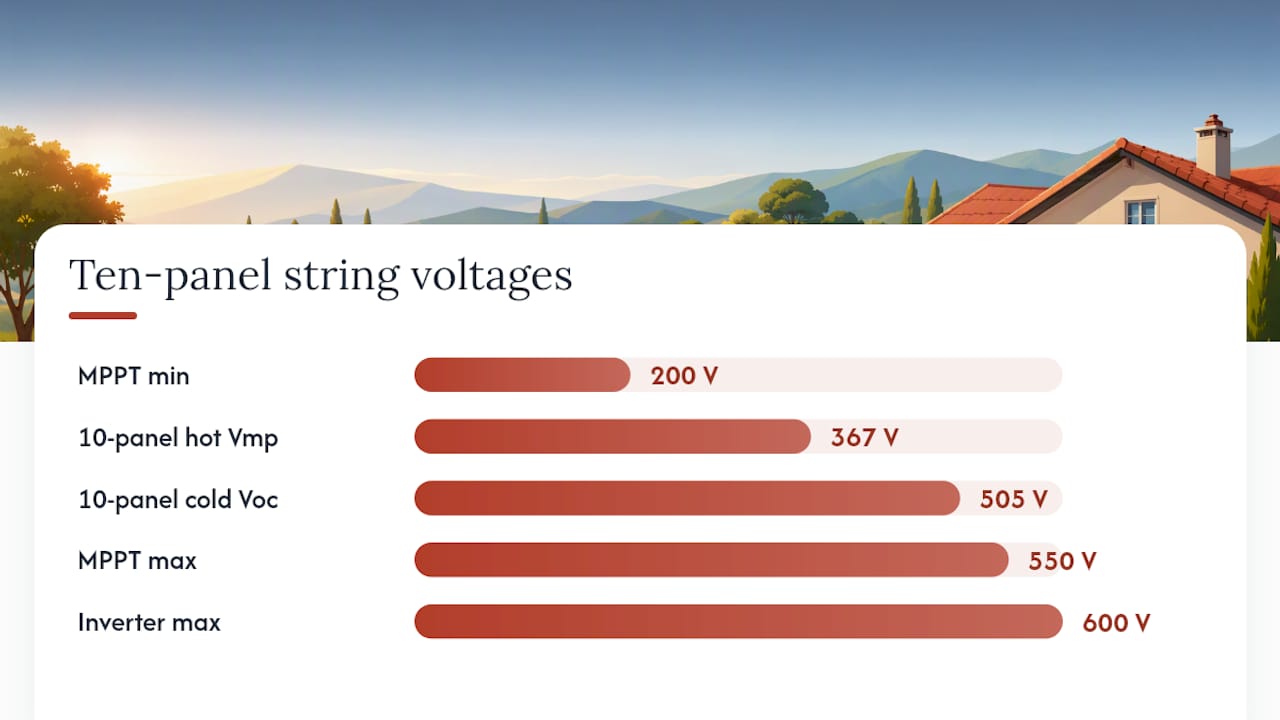
At a Tmin of minus 10°C, that’s 35 degrees below the 25°C test point. Voc_cold works out to roughly 46.3 × [1 + (0.0026 × 35)] = 50.5V per panel. Ten panels in series gives 505V cold Voc, comfortably under a typical residential inverter’s 600V maximum input. At a Tmax of 45°C, 20 degrees above test conditions, Vmp drops to roughly 38.7 × [1 − (0.0026 × 20)] = 36.7V per panel, or 367V for ten panels in series, which sits well inside a typical 200 to 550V MPPT window. That string passes both checks. Running the same maths at 14 panels would push cold Voc past 700V on many inverters, which is why manufacturers publish these correction methods rather than leaving installers to eyeball it.
Pro Tip: Never use the manufacturer’s “nameplate” Tmin from a mild climate zone as your design figure. Pull actual historical low temperatures for the installation postcode and add a margin, because a string that passes on paper at minus 5°C can exceed the inverter’s input rating on the one morning it actually hits minus 12°C.
Which wiring components sit between the panels and the inverter?
A string is more than cable and connectors. Between the last panel and the inverter’s terminals sits a chain of hardware each with its own current rating, and any weak link in that chain becomes the actual limit on your design, regardless of what the panels and inverter can theoretically handle.
| Component | Function | Key rating to check |
|---|---|---|
| MC4 connectors | Join panel leads into a continuous string | Current rating, IP rating for outdoor use |
| Y-branch connectors | Combine two parallel leads into one before a combiner | Current rating, must exceed combined Isc |
| Combiner box | Brings multiple strings together before the inverter | Busbar current rating, number of string inputs |
| String fuse / OCPD | Protects each string from reverse current fault | Rated to manufacturer’s maximum series fuse spec |
| DC isolator | Allows safe disconnection for maintenance | Voltage and current rating matched to array |
| Earthing / bonding | Protects against fault currents and lightning-induced surges | Compliance with local wiring regulations |
| Rapid shutdown device | Drops array voltage to a safe level on command | Compliance with applicable rapid-shutdown rules |
Wire sizing follows a simple rule of thumb: size the conductor for the string’s Isc multiplied by a safety factor (commonly 1.25), then check the round-trip cable run for voltage drop. Series wiring actually helps here: pushing voltage up and keeping current at single-module levels lets you use a smaller conductor over the same distance than an equivalent parallel run would need, a point covered in detail in The Green Watt’s wiring guide.
Small MC4 plug connectors are rated for a single string’s current, not for two or three strings merged together. Combining parallel strings through a chain of Y-connectors instead of a properly rated combiner box is one of the more common ways installers accidentally exceed a connector’s current rating, and it’s exactly the kind of shortcut a PV string and combiner reference flags as a design fault during review. Label every string clearly at the combiner and at the inverter input, and follow the manufacturer’s installation manual and your local wiring regulations rather than a generic rule of thumb picked up online.
How does shading affect string performance?
Shade doesn’t reduce output proportionally. In a series string, the panel receiving the least light sets the current ceiling for every other panel in that string, because current can only flow at the rate the weakest link allows. A single chimney shadow crossing one corner panel for twenty minutes a day can drag down the output of nine unshaded panels wired in series alongside it. Parallel strings isolate this to some degree, since a shaded string’s poor performance doesn’t drag down a separate parallel string, but combining strings still raises the current and protection requirements at the combiner.
Several mitigation approaches exist, each with a different cost and wiring implication:
- Bypass diodes, built into almost every panel, route current around a shaded cell group rather than blocking the whole panel. They help within a single panel but don’t solve string-level shading between panels.
- Module-level power electronics, commonly called optimisers, sit behind each panel and manage its output independently before sending power to a central string inverter, reducing mismatch losses without needing a full microinverter swap.
- Microinverters, fitted individually behind each panel, convert DC to AC at the module itself, so one shaded panel has zero effect on its neighbours.
- Separate MPPT inputs on a multi-MPPT string inverter let you dedicate one input to a shaded or differently-angled section of roof, keeping it electrically independent from the unshaded majority.
The decision flow is fairly blunt in practice. A single unshaded south-facing plane rarely justifies the extra cost of optimisers or microinverters; straightforward series-parallel strings on a standard string inverter do the job. A roof with dormers, chimneys, or two distinct orientations changes the calculation, and that’s where separate MPPTs or module-level electronics start paying for themselves in recovered yield. Our guide to solar panel shading covers the yield impact in more depth if your roof has any obstructions worth mapping first.
Two worked examples: single-plane and mixed-plane roofs
At Tmin of minus 10°C, cold Voc reaches roughly 505V, well under the 600V ceiling. At Tmax of 45°C, hot Vmp falls to roughly 367V, comfortably inside the MPPT window. Current stays at 10.6A, under the inverter’s typical 15A per-MPPT rating. This string passes every check.
Example 2: mixed-plane roof, east and west facing. Twelve panels split into two identical series strings of six panels each, one per roof plane, both feeding separate MPPT inputs on the same inverter, or paralleled together if the inverter only offers one MPPT and both planes receive similar irradiance timing. Each six-panel string at Tmin minus 10°C reaches roughly 303V cold Voc, safely under a 600V inverter maximum. Paralleling two such strings on one MPPT input pushes combined current to roughly 21.2A, which would exceed a single 15A MPPT input rating and force separate inputs or a larger combiner with appropriately rated fusing.
The second example is a genuinely common trap. The voltage maths looks fine on paper for both strings individually, but combining them onto one input without checking combined current is exactly how installers end up nuisance-tripping an MPPT input fuse within the first few weeks of operation. Running your own numbers through the LBL PVTools string length calculator before ordering equipment catches this kind of error for free.
What should you check before switching the system on?
Commissioning is where paper calculations meet reality, and it’s the last chance to catch a wiring mistake before it becomes a warranty claim. Work through this before signing off any installation:
- Verify every string is labelled clearly at the combiner box and at the inverter’s DC input terminals.
- Measure open-circuit voltage per string with a multimeter before connecting to the inverter, ideally on a cool morning, and compare it against your calculated cold Voc.
- Confirm the inverter wakes and begins tracking at the expected MPPT start voltage once connected.
- Inspect every MC4 connection for full engagement and correct torque, since a loose connector is a common source of arcing faults.
- Check that string fuses or other overcurrent protection devices (OCPD) match the manufacturer’s maximum series fuse rating.
- Test the rapid shutdown function where fitted, confirming voltage drops to the required safe level within the specified time.
Several mistakes turn up repeatedly during professional plan review. Using an optimistic Tmin figure instead of the site’s actual record low is the most common, followed by mixing module types on the same string, running unprotected parallel strings without adequate fusing, undersizing the cable run into the combiner, skipping string labels entirely, and leaving MC4 connectors under-torqued. Each has a one-line fix: pull real climate data, keep strings uniform, fuse every parallel branch, size cable to Isc plus a safety margin, label everything, and torque connectors to the manufacturer’s spec. Hand the homeowner a written record of as-built string counts, the datasheets used for calculations, and the physical location of every isolator and shut-off before leaving site.
How do installers actually plan string routing on a real roof?
Every competent layout starts the same way: survey each roof plane’s azimuth and tilt separately, walk the site at different times of day to map shading windows across the seasons, group identical panels onto the same MPPT wherever possible, keep paralleled string lengths identical, and route cable to the combiner by the shortest practical path.

Two scenarios come up constantly. On a single south-facing roof with no obstructions, the job is straightforward: calculate the maximum series string length the inverter’s voltage window allows, split the total panel count into equal strings of that length, and feed them into as few MPPT inputs as the inverter offers. On a roof with two distinct planes, say a main pitch facing southeast and a smaller dormer facing southwest, the temptation is to force both into a single string to save an MPPT input. Resist it. Splitting them onto separate MPPTs, or fitting optimisers if the inverter only has one MPPT input, recovers yield that a combined string would lose when one plane shades before the other.
Pro Tip: Always design to the coldest plausible morning, not the average one. I’ve seen strings sized against a mild regional average Tmin trip an inverter’s overvoltage protection on the one hard frost of the year, simply because nobody checked the actual record low for that postcode before ordering equipment.
What are the safety and regulatory basics to know?
Work on de-energised circuits wherever the task allows, and never assume a disconnected inverter means the DC side is safe. Fit the correct overcurrent protection for every combiner box, install earthing and DC isolators at every required point, and label them clearly, and follow whatever rapid-shutdown requirements apply in your area. These aren’t optional extras; they’re the difference between a system that fails safely and one that doesn’t.
Bring in a qualified installer if you can’t confidently run the temperature correction calculations yourself, can’t get hold of the actual datasheets rather than marketing brochures, or the array spans multiple roof planes where MPPT allocation and combined current checks get genuinely complex. The maths in this article is entirely reproducible with the right datasheets and a calculator, but a live rooftop with real weather, real shading, and real fault conditions punishes a wrong assumption far more than a spreadsheet does. Always consult the manufacturer’s installation manual and the wiring regulations that apply in your area for binding requirements. This article gives general technical guidance, not a substitute for professional advice.
Why does Smarthometechnical favour conservative string margins?
Solar panel installation, done properly, means you’ll never see most of the calculation work that went into a functioning system. That’s rather the point. When Smarthometechnical designs a string layout for a home in Dorset, Hampshire, or Devon, we’re building in margin against the coldest morning that roof has ever seen, not the average one, because the average morning was never the risk. For readers weighing up a mixed-plane roof or a battery pairing alongside solar, our guide to combined solar and battery systems and GivEnergy support page cover how string design choices carry through into hybrid inverter setups. If your roof has more than one plane, or you’re unsure whether your existing strings are sized correctly, get in touch with our solar installation team for a proper site survey rather than guessing from a rooftop photo.
Frequently asked questions
What is a solar string configuration in simple terms?
It’s how solar panels are wired together, in series, parallel, or a mix of both, to produce a voltage and current combination that matches what a specific inverter is designed to accept.
How many panels can go in one string?
It depends entirely on the inverter’s maximum DC input voltage and MPPT range combined with the module’s Voc and temperature coefficient, but residential strings commonly run between eight and twenty panels.
What happens if a string voltage is too high for the inverter?
The inverter can suffer permanent damage to its input components, and in most cases the manufacturer’s warranty won’t cover a fault caused by exceeding the rated maximum input voltage.
Do all panels in a string need to be identical?
Yes. Mixing different wattages or electrical specifications in the same series string means the weakest panel limits the output of every other panel in that string.
Is series or parallel wiring better for a shaded roof?
Neither wiring type alone solves shading well; module-level power electronics or microinverters, combined with separate MPPT inputs for differently-shaded sections, handle shaded roofs far more effectively than choosing series over parallel.
Sources
- Energy
- String length calculator | PVTools (LBL)
- Solar panel wiring basics: How to wire solar panels | Aurora Solar
- How to Wire Solar Panels in Series or Parallel: Voltage, Current, Shade, and Safety — NerdVolt
- How to wire solar panels | The Green Watt
