
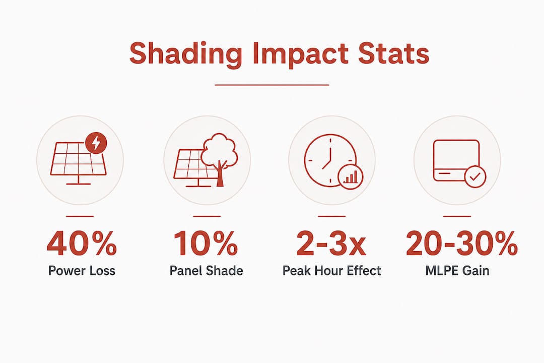
Shading is defined as the obstruction of sunlight reaching solar cells, and it is the single most damaging factor affecting solar panel efficiency and energy yield. The role of solar panel shading goes far beyond simple light reduction. Shading just 10% of a panel’s surface can cut power output by 30–40% in traditional string inverter systems. That disproportionate loss is the result of how solar cells connect electrically, not just how much sunlight they receive. Property owners and developers who understand this relationship make better decisions before, during, and after installation.
How does shading physically and electrically affect solar panel performance?
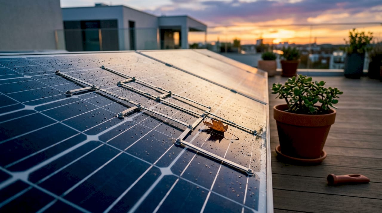
Solar panels are built from cells wired in series, meaning current flows through each cell in sequence like links in a chain. When one cell is shaded, it restricts current flow for every other cell in that string. The unshaded cells cannot compensate. The entire string drops to the output level of the weakest cell.
Bypass diodes exist to manage this problem. Bypass diodes protect shaded cells by routing current around shaded groups, but this comes at a cost. A typical 60-cell module contains three bypass diode groups. When one group activates, the output for that entire group is lost, typically one-third of the module’s capacity. The diode protects the hardware but sacrifices production.
The electrical consequence runs deeper than most property owners expect. Shading distorts the current-voltage (IV) curve of the array, creating multiple local power peaks. Standard Maximum Power Point Tracking (MPPT) algorithms in string inverters often lock onto a suboptimal peak. This means the inverter is not extracting the maximum available power even from the unshaded cells.
- Series string effect: One shaded cell limits current for the whole string, not just itself.
- Bypass diode activation: Protects cells from damage but removes one-third of a module’s output per activated group.
- IV curve distortion: Creates multiple power peaks, confusing MPPT algorithms and reducing total harvest.
- Thermal hotspots: A fully shaded cell acts as a resistive load, dissipating power as heat. This accelerates module degradation and, in severe cases, creates a fire risk.
Pro Tip: If your installer mentions “string inverter” and your roof has any chimney stacks, dormer windows, or neighbouring trees, ask specifically how shading losses have been modelled for your site. The answer will tell you a great deal about the quality of the design.
What factors influence the severity of shading losses?
Not all shade is equal. The timing, geometry, and electrical layout of your system all determine how badly shading hurts your annual yield.
Timing matters more than area
Shading during peak sun hours between 10 AM and 2 PM causes 2–3 times more energy loss than the same shading at dawn or dusk. A chimney that casts a shadow across your panels at noon is far more damaging than a tree that shades the array at 8 AM. This is why the direction and movement of shadows across a roof matters as much as their size.
Near shading versus far shading
Near shading comes from objects close to the array: chimneys, aerials, dormer windows, and trees. Far shading comes from the horizon, distant hills, or tall buildings. Near shading is more severe because it creates concentrated shadow patterns directly on cells. Far shading tends to reduce irradiance more uniformly and is easier to model and predict.
How array layout and panel technology affect losses
The electrical configuration of arrays determines shading severity, making layout design as critical as hardware choice. Series-connected strings amplify shading losses. Parallel connections reduce them. More complex topologies like Total Cross Tied (TCT) configurations distribute shading effects across the array, reducing the impact on any single string.
| Factor | Lower shading loss | Higher shading loss |
|---|---|---|
| Shading time | Early morning or late afternoon | 10 AM to 2 PM peak hours |
| Shading type | Far shading (horizon, terrain) | Near shading (chimneys, trees) |
| Panel technology | Half-cut cell or shingled panels | Standard full-cell panels |
| Inverter type | Microinverters or DC optimisers | Traditional string inverters |
| Array layout | TCT or parallel configurations | Series string configurations |
Half-cut cell panels split each cell in two, halving the current and reducing resistive losses under partial shade. Shingled panels remove gaps between cells entirely, improving shade tolerance further. Both technologies outperform standard full-cell panels when partial shading is unavoidable.
What mitigation strategies and technologies manage shading effectively?
The most effective approach to reducing shading losses combines hardware selection with layout design. No single solution fits every site.
Module-level power electronics (MLPE)
Microinverters and DC optimisers are collectively known as module-level power electronics, or MLPE. They operate independently at each panel rather than across a whole string. MLPE hardware limits shading losses to only the affected panels. In a 10-panel string, a single shaded panel causes 50–80% power loss with a string inverter. With MLPE, that same panel causes only 15–20% loss, and the remaining nine panels continue producing at full capacity.
Microinverters and DC optimisers can recover 20–30% of annual production on shaded roofs compared to string inverters. That figure represents a meaningful financial difference over a 25-year system lifetime.
Array reconfiguration strategies
For larger installations, array reconfiguration offers another route to reducing losses without adding electronics to every panel. Novel Ramanujan Reconfiguration reduces shading losses by up to 77.77% compared to conventional layouts. This technique rearranges the physical or electrical position of panels so that shading falls across multiple strings rather than concentrating on one. The result is a more even distribution of losses across the array. Developers working on ground-mounted or large commercial rooftop systems should ask their installer about reconfiguration strategies during the design phase.
| Technology | Best suited for | Key benefit |
|---|---|---|
| String inverter | Unshaded, simple roofs | Lower upfront cost |
| DC optimisers | Moderate shading, mixed orientations | Panel-level MPPT, retrofit-friendly |
| Microinverters | Complex shading, multiple roof planes | Full panel independence, monitoring per panel |
| Half-cut cell panels | Any shaded site | Reduced resistive losses, better partial shade tolerance |
| TCT array layout | Large arrays with complex shading | Distributes losses, no additional electronics needed |
Pro Tip: For sites where shading is unavoidable between 10 AM and 2 PM, prioritise MLPE over panel upgrades alone. The inverter choice has a greater impact on yield recovery than panel technology in most real-world shading scenarios.
You can read more about solar panel installation options and how Smarthometechnical approaches system design for shaded sites.
How can you assess and plan for shading before installation?
Shading is the most predictable yet often ignored factor in site analysis. Addressing it before installation costs far less than correcting it afterwards.
A thorough shading assessment follows a clear sequence:
- On-site survey: A qualified assessor visits the property and records all potential shading objects, their heights, distances, and seasonal movement. This is the foundation of any reliable analysis.
- Drone imagery: Aerial photography captures roof geometry, nearby obstructions, and horizon profiles with accuracy that ground surveys alone cannot match. This is particularly useful for complex roofs or large commercial sites.
- 3D digital twin modelling: Software tools including Aurora Solar create a three-dimensional model of the site and simulate sun paths across every hour of the year. Professional 3D shading analysis achieves ±2–3% accuracy, making it reliable enough for financial modelling and investment decisions.
- Loss threshold assessment: Annual shading losses range from 1–5% for well-sited systems and 20–30% for urban rooftops. Industry guidance treats losses above 4–5% as a trigger for redesign or MLPE deployment. If your site exceeds this threshold, the design needs to change before installation begins.
- Financial integration: Shading losses feed directly into yield projections and payback calculations. A site modelled with accurate shading data produces financial forecasts that hold up over the system’s lifetime. A site modelled without it produces disputes.
Integrating shading analysis early in the planning process protects both the property owner and the installer. Post-installation disputes over underperformance are almost always rooted in inadequate pre-installation assessment. For a broader view of how planning affects outcomes, the solar planning guide from Smarthometechnical covers the full process in practical terms. The energy sector’s growing focus on accurate pre-installation assessment reflects how much energy project outcomes depend on getting this stage right.
Key takeaways
Shading causes disproportionate power losses through electrical string effects, and addressing it with the right hardware and layout design is the most reliable way to protect solar investment returns.
| Point | Details |
|---|---|
| Shading losses are non-linear | Shading 10% of panel area can cause 30–40% power loss in string inverter systems. |
| Timing of shade is critical | Shade between 10 AM and 2 PM causes 2–3 times more loss than shade at dawn or dusk. |
| MLPE recovers significant yield | Microinverters and DC optimisers recover 20–30% of annual production on shaded roofs. |
| Layout design reduces losses | Array configurations like TCT and Novel Ramanujan Reconfiguration cut losses without extra electronics. |
| Pre-installation analysis prevents disputes | Professional 3D shading analysis at ±2–3% accuracy is the standard for reliable financial modelling. |
What I’ve learned about shading that most installers underestimate
Shading is the most underestimated cause of yield loss I encounter on real projects. Property owners often accept a vague assurance that “a bit of shade won’t matter much,” and then spend years wondering why their system underperforms against the original projection.
The non-linear nature of shading losses is the part that catches people out. Most people assume that 10% shade means 10% less power. The reality, where 10% shade can mean 30–40% less output, is genuinely surprising. Installers who do not model this accurately are not being dishonest. They are often working with tools that do not capture the electrical behaviour of the string.
What has changed recently is the quality of reconfiguration strategies. Novel Ramanujan Reconfiguration is not a marketing term. It is a mathematically grounded approach to distributing shade across an array, and the performance gains are substantial. For larger installations, it deserves serious consideration alongside MLPE hardware.
My consistent advice is this: if your site has any meaningful shading between 10 AM and 2 PM, treat MLPE as a baseline requirement rather than an optional upgrade. The yield recovery over 25 years will almost always justify the additional upfront cost. Accurate shading analysis is not a luxury. It is the foundation of a project that performs as promised.
— Simon
How Smarthometechnical approaches shading for solar installations
Shading analysis is built into every solar installation Smarthometechnical designs, not added as an afterthought. The team uses 3D modelling to simulate sun paths across your specific site, identifying shading risks before a single panel is ordered.

Smarthometechnical installs half-cut cell panels, microinverters, and DC optimisers as standard options for sites where shading is a factor. Every system is designed around your roof’s actual shading profile, not a generic template. If your site sits in an urban area or has complex roof geometry, the design will reflect that reality. Explore professional solar installation services from Smarthometechnical and find out what a properly assessed system looks like for your property.
FAQ
How much can shading reduce solar panel output?
Shading just 10% of a panel’s surface can reduce power output by 30–40% in string inverter systems due to series string effects. The loss is disproportionate because one shaded cell restricts current for the entire string.
What is the acceptable level of shading loss for a solar installation?
Annual shading losses below 4–5% are generally acceptable for well-sited systems. Losses above this threshold trigger a redesign or the deployment of MLPE hardware to protect yield.
Do microinverters really make a difference for shaded roofs?
Microinverters and DC optimisers recover 20–30% of annual production on shaded roofs compared to string inverters. They limit losses to the affected panel only, leaving the rest of the array unaffected.
What is Novel Ramanujan Reconfiguration?
Novel Ramanujan Reconfiguration is an advanced array layout strategy that redistributes shading effects across multiple strings rather than concentrating them on one. It reduces shading losses by up to 77.77% compared to conventional layouts.
When should shading analysis happen in a solar project?
Shading analysis must happen before installation begins. Professional 3D shading analysis achieves ±2–3% accuracy and feeds directly into yield projections and financial modelling, preventing post-installation disputes over underperformance.
