
Gaps between solar panels are not an aesthetic choice. They are a structural and electrical necessity, and getting them wrong can crack cells, void warranties, and in severe cases create a fire risk. If you own a domestic solar PV system in the UK, here is what to check right now:
- Visual check: Walk the roofline or use binoculars. Can you see any two panels touching, or any cracked glass and bubbling on the back surface?
- Measure the gap: Frame-to-frame spacing between adjacent modules should typically be at least a small but sufficient gap to allow for thermal expansion, commonly in the range of a few millimeters to a few centimeters. Less than that warrants a call to your installer.
- Contact your installer if: gaps appear to be under the manufacturer’s recommended minimum, you can see contact marks between frames, or your system’s output has dropped unexpectedly.
Watch for these warning signs in particular: cracked glass along a panel edge, a bubbled or discoloured backsheet, or a sudden unexplained drop in generation on your monitoring app. Any one of them suggests a spacing or hotspot problem that needs professional attention.
Key takeaways
Correct expansion gaps between solar panels prevent mechanical stress, hotspot formation, and warranty voidance, making spacing one of the most consequential decisions in any domestic PV installation.
| Point | Details |
|---|---|
| Minimum gap guidance | Adjacent modules typically need 10–30 mm clearance; always check your module’s datasheet for the binding figure. |
| Thermal movement is real | Aluminium frames elongate measurably over typical temperature rises, making gap allowance a structural necessity. |
| Tight spacing causes hotspots | Microcracks from frame stress can produce hotspots that reduce module power by around 25% in affected sub-strings. |
| Document from day one | Date-stamped photos and monitoring logs are your evidence base for warranty and insurance claims. |
| Smarthometechnical | Provides MCS-accredited spacing inspections and solar installations across Dorset, Hampshire, and Devon. |
Table of Contents
- Why solar panel gaps matter: the purpose of expansion clearance
- Why panels expand and move: the physics behind the gap
- What goes wrong when panels are too tight
- How tight spacing contributes to destructive heating
- How much gap should there be between panels?
- Standards, datasheets, warranties and UK compliance
- Common installer mistakes and how to inspect your own system
- Can spacing be fixed after installation?
- How spacing defects affect warranties and insurance
- How Smarthometechnical fits and protects spacing
- The real cost of getting spacing wrong
- Smarthometechnical spacing inspections: what to expect
- Useful documents and where to find them
- Sources
Why solar panel gaps matter: the purpose of expansion clearance
The technical term is expansion gap or installation clearance, and it refers to the deliberate physical space left between the aluminium frames of adjacent modules and between rows of panels. It is not wasted space.
Those gaps serve several functions simultaneously:
- Thermal expansion allowance: Aluminium frames and silicon cells expand at very different rates as temperature changes, making gaps necessary to accommodate these movements without stress.
- Airflow and cooling: Air circulating beneath and between panels carries heat away from the backsheet, keeping operating temperatures lower and output higher.
- Drainage: Water needs a clear path off the roof. Tight packing traps moisture at frame joints, accelerating corrosion and seal degradation.
- Maintenance access: Technicians need to reach clamps, flashings, and cable runs without levering against module glass.
- Abrasion prevention: Frame edges in contact will wear against each other in wind, eventually breaching the anodised coating and exposing bare aluminium to corrosion.
In practice, you will see these gaps as a few millimetres to a few centimetres of visible clearance between panel frames. On a well-installed pitched roof, the spacing looks deliberate and consistent. Uneven or absent gaps are a red flag.
Why panels expand and move: the physics behind the gap
Solar panels spend their lives cycling between cold damp mornings and hot summer afternoons. In the UK, a panel on a south-facing roof can reach 70–80 °C on a clear July day and drop close to freezing overnight in winter. That temperature swing drives real physical movement.
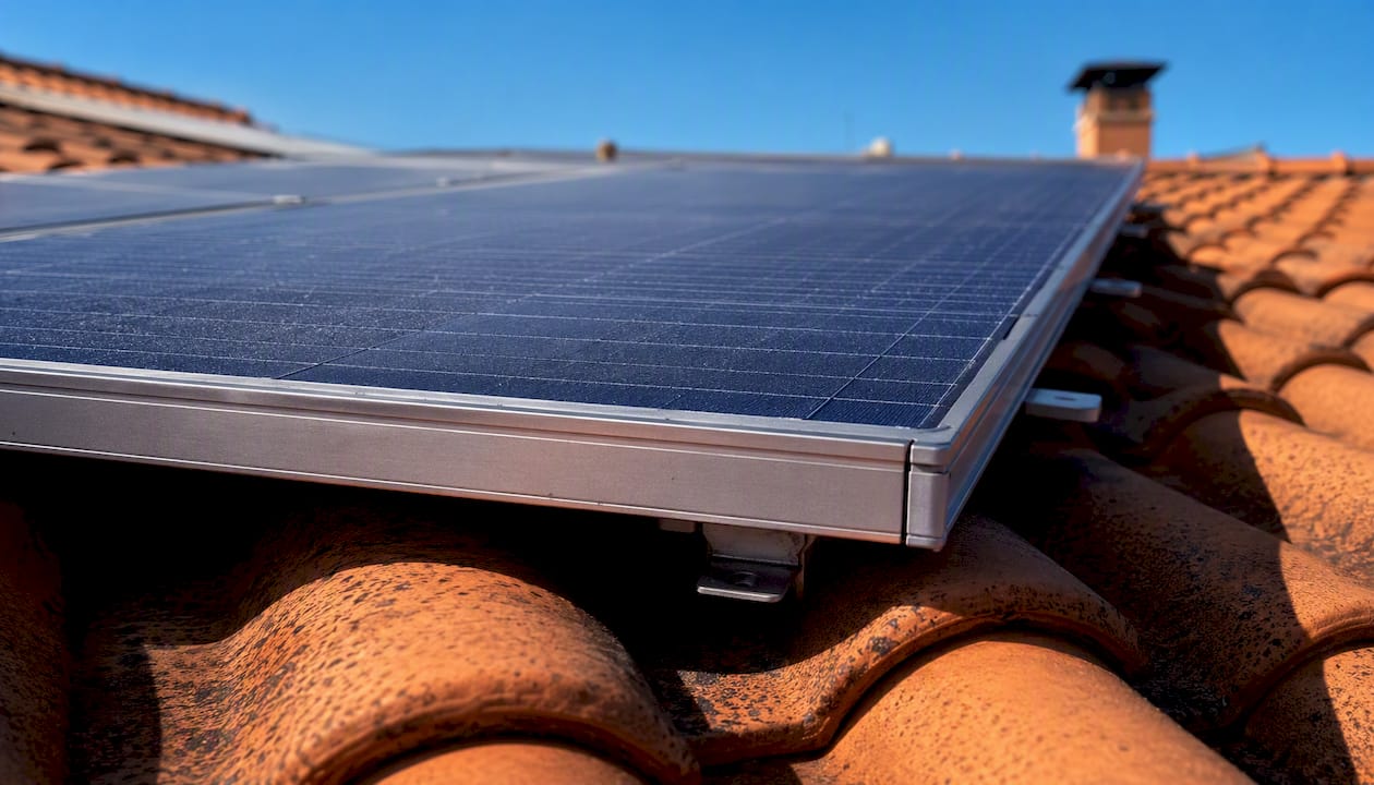
The core issue is a mismatch in how different materials respond to heat. Aluminium frames expand far more than silicon cells: aluminium has a significantly higher coefficient of thermal expansion compared to silicon. On a typical frame length, temperature rises produce measurable elongation in aluminium, while the silicon cell laminate expands much less. The silicon cell laminate inside that frame barely moves. Without a gap, the frame has nowhere to go except into the adjacent module.
Several other factors compound this:
- Diurnal cycling: Daily heating and cooling cycles mean the frame is in constant low-level motion. Over years, this fatigue accumulates.
- Seasonal extremes: UK winters bring snow loading that compresses the array; summers bring thermal peaks. Both push frames toward their neighbours.
- Wind flex: Panels on exposed roofs flex slightly in gusts. Without clearance, that flex transfers directly into the neighbouring module’s frame.
- Moisture cycles: Freeze-thaw cycles in winter can cause slight swelling at frame joints, adding mechanical stress to an already tight array.
Understanding how solar performs in winter helps explain why cold-weather stresses are just as relevant as summer heat when thinking about spacing.
What goes wrong when panels are too tight
Insufficient spacing creates a chain of failures, starting mechanical and quickly becoming electrical.
Mechanical failures:
- Microcracks: Frame stress transfers into the cell laminate. Field observations indicate that spacing below a certain threshold increases the probability of microcrack formation in cells due to frame stress transfer., and microcracks are invisible to the naked eye until they have already degraded output.
- Frame bending and abrasion: Frames in contact grind against each other in wind, wearing through protective coatings.
- Seal and laminate delamination: Compressed edges force moisture pathways open at the frame-to-glass seal, allowing water ingress into the laminate.
Electrical consequences:
- Hotspots: A microcracked or partially shaded cell in a series string can be driven into reverse bias, dissipating power as heat rather than electricity. Hotspot heating can cause localized overheating, potentially damaging cells, glass, and encapsulant, with severe cases posing a fire risk..
- Bypass diode activation: Bypass diodes protect against hotspots but at the cost of cutting out a section of the module. Output drops every time a diode fires.
- String mismatch: One degraded module pulls down the output of every other module in its string.
Statistic to note: Research has documented cases where hotspot-affected sub-strings produced around 25% power loss in a single module, with temperature surges recorded in controlled tests.
Safety and operational risks:
- Accelerated degradation shortens the system’s effective life well before the 25-year performance warranty expires.
- Severe hotspots can reach temperatures that melt backsheet material. Partial shading, soiling and rooftop conditions are recognised drivers of this kind of overheating.
- Water ingress from failed seals can cause inverter trips and arc faults.
How tight spacing contributes to destructive heating
Hotspot formation follows a specific mechanism worth understanding. In a series-connected string of cells, current must be the same through every cell. When one cell produces less current than its neighbours (because it is shaded, soiled, or microcracked), the string forces current through it in reverse. That cell then dissipates the string’s power as heat rather than generating electricity.
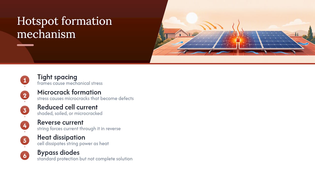
The link to spacing is direct. A combination of mechanical stress and operational shading increases the chance that a microcrack will develop into a permanent electrical defect that continues generating hotspots even after the original shading clears. Tight frames cause the stress; the stress causes the crack; the crack causes the hotspot.
Bypass diodes are the standard protection mechanism, but they are not a complete solution. Some panel architectures are engineered to distribute reverse-bias energy more evenly, reducing hotspot severity, but standard panels still depend on diodes as a last line of defence. Correct spacing reduces the mechanical stress that creates the cracks in the first place, making it a more fundamental protection than any diode circuit.
For a broader look at how shading affects solar output, the interaction between physical damage and operational shading is worth reading in full.
How much gap should there be between panels?
There is no single universal figure, but practical guidance converges on a workable range. Industry guidance commonly recommends adjacent-module gaps of around 10–30 mm, with larger row-to-row clearances to permit airflow, drainage and maintenance access.
The factors that shift the recommendation:
- Module frame length: Longer frames expand more in absolute terms, so larger panels need slightly more clearance.
- Roof slope: Steeper pitches drain naturally; flat or low-pitch roofs need more drainage clearance between rows.
- Wind and snow loads: Exposed sites in the UK (coastal, upland) need spacing that accommodates greater flex and loading.
- Mounting type: Penetrating rail systems and ballasted flat-roof systems have different movement characteristics and different manufacturer requirements.
- Manufacturer datasheet: This is the binding reference. Some modules specify 5 mm minimum; others require 20 mm or more. Always check the datasheet for your specific model.
For flat roofs specifically, guidance recommends row clearances of around 5–10 cm for drainage and airflow, with adjacent module gaps of a few millimetres to a few centimetres depending on layout.
Pro Tip: Measure frame-to-frame at the mid-span of the long edge, not at the corners. Corner clamps can create a slightly wider gap at the ends while the mid-span is actually touching. Mid-span is where thermal stress concentrates.
Standards, datasheets, warranties and UK compliance
The manufacturer’s module datasheet and the racking system’s installation manual are the primary legal references for spacing. They define the minimum and maximum gaps, the approved clamp types, and the torque specifications. Deviating from them is not just poor practice; it can void the module warranty and the racking guarantee.
Key documents and checks for UK homeowners:
- Module datasheet: States minimum frame clearances, approved mounting zones, and any restrictions on clamp placement. Your installer should have provided this at handover.
- Racking manufacturer’s manual: Specifies rail lengths, clamp spacing, and expansion allowances for the specific mounting system used.
- MCS certificate: MCS accreditation confirms your installer met the Microgeneration Certification Scheme’s standards. An MCS-certified installation comes with a workmanship guarantee and a route to dispute resolution if the work is defective.
- Installer workmanship guarantee: Separate from the product warranties, this covers the quality of the installation itself. Check whether spacing defects would be covered.
- Method statement: A compliant installer should have documented their spacing approach during planning. Ask for this if you do not have it.
If you need to make a warranty claim, the evidence that matters is: date-stamped photographs of the gap (or lack of it), your monitoring system’s output logs showing when the problem started, and any written communications with your installer. Collect these before contacting the manufacturer.
Common installer mistakes and how to inspect your own system
Most spacing problems come from a handful of recurring errors:
- Gaps squeezed during installation to fit more panels on a roof, or to avoid cutting a rail to length.
- Incorrect clamp spacing that allows the module to shift after installation.
- Using rails that are too short for the array, forcing panels closer together than the design intended.
- Over-torquing frame fastenings, which compresses the frame against the clamp and indirectly stresses adjacent modules.
Your inspection checklist:
- Measure visible frame-to-frame gaps with a ruler or tape. Anything under 10 mm deserves a closer look; anything under 5 mm is urgent.
- Look for contact marks: shiny wear lines on frame edges where anodising has been abraded.
- Check for cracked glass, particularly along panel edges near clamps.
- Look at the backsheet (the underside of the panel, visible from the loft or with a mirror on a pole). Bubbling, discolouration, or delamination are serious signs.
- Check bolt heads for signs of stripping or corrosion that might indicate over-torquing.
Treat as urgent: visible glass cracks, backsheet deformation, or a rapid unexplained output drop of more than 10–15% that your monitoring system cannot explain by weather. These warrant a professional inspection, not a wait-and-see approach.
Pro Tip: Your inverter or monitoring app often shows the first sign of a spacing problem before it is visible. A single string underperforming relative to others on the same roof, on a clear day, is worth investigating.
For a structured approach to fault finding on solar systems, a professional thermal imaging check can confirm hotspots that are invisible to the eye.
Can spacing be fixed after installation?
Yes, in most cases, though the right approach depends on how the system was originally mounted.
Practical retrofit options:
- Clamp re-spacing: Where rails are long enough, a qualified installer can reposition mid-clamps to restore the correct gap. This is the most common fix.
- Spacer blocks: Manufacturer-approved spacer blocks can be inserted between frames to maintain minimum clearance without moving the entire array.
- Rail replacement: If rails are too short and panels are crowded as a result, replacing with correctly sized rails is the proper solution, not a workaround.
- Professional re-torque: Fastenings that have been over-tightened need to be backed off to the correct torque specification and, where threads are damaged, replaced.
- Resealing flashings: Where water ingress has already occurred at frame joints, flashings need to be resealed by a qualified roofer or solar installer.
When partial rework is better than adjustment: If frames have already been deformed by contact, or if the laminate shows signs of delamination, adjusting the gap alone will not undo the damage. Partial module replacement may be necessary.
What to avoid:
- DIY drilling near module frames. Any penetration near the laminate risks immediate electrical damage.
- Adhesive fillers between frames. These trap moisture and prevent the thermal movement the gap was designed to allow.
- Rough cleaning with abrasive tools near frame edges. This stresses already-compromised seals and can introduce new microcracks.
How spacing defects affect warranties and insurance
Most module warranties and racking guarantees contain a clause requiring installation to follow the manufacturer’s instructions. Non-compliance, including incorrect spacing, can void the relevant section of cover. This matters because a microcrack-driven output loss that develops five years after installation may be traceable to an installation defect, and if the spacing was wrong from day one, the manufacturer has grounds to decline the claim.
Protecting your position:
- Photograph the installed array on the day of commissioning, with visible frame gaps. Date-stamp the images.
- Keep your monitoring system’s production logs. A sudden step-change in output is evidence that something changed on a specific date.
- Report concerns to your installer in writing (email is fine) as soon as you notice them. This creates a timestamped record.
- Ask your installer for a written spacing confirmation as part of the handover pack.
Insurance considerations: A structural failure caused by frame deformation, or a fire resulting from a severe hotspot, is potentially relevant to your household insurer. Insurers may ask for evidence that the system was installed to the manufacturer’s specification. A professional inspection report from an MCS-accredited installer, confirming spacing compliance, is the strongest evidence you can hold.
How Smarthometechnical fits and protects spacing
At Smarthometechnical, spacing is checked at three stages: design, installation, and commissioning.
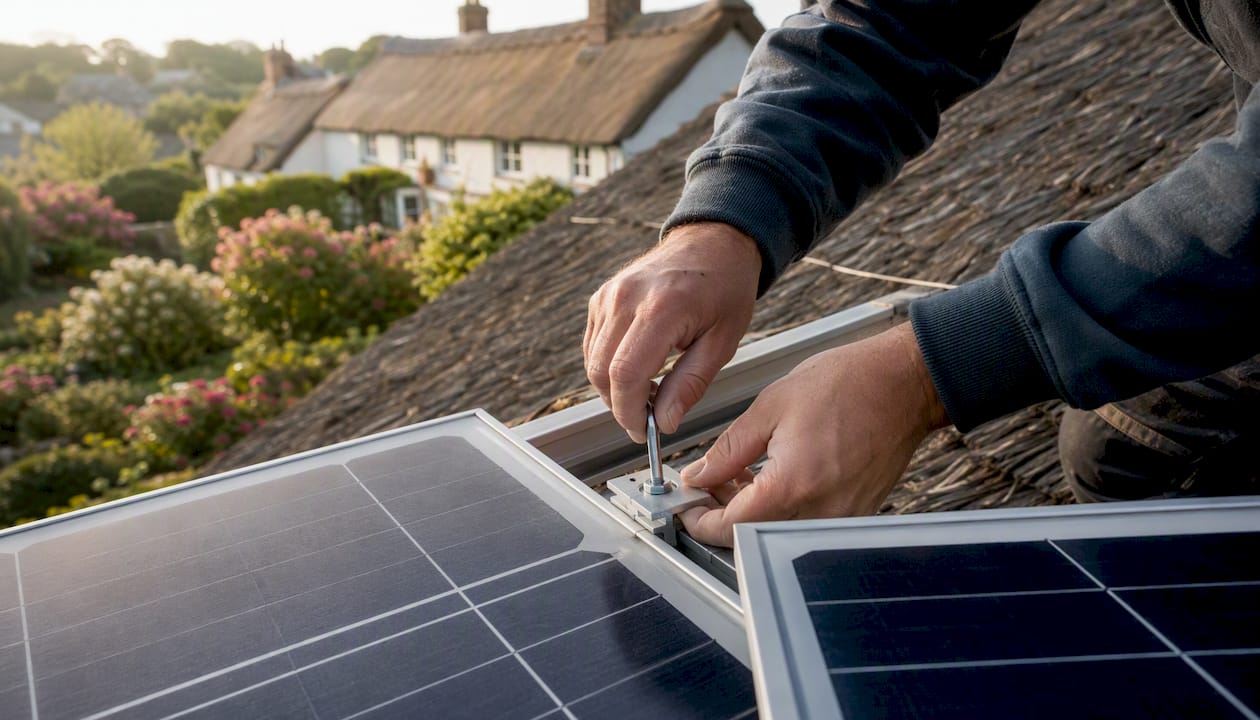
During design, the module datasheet and racking manufacturer’s manual are reviewed together. Rail lengths are specified to deliver the correct frame-to-frame clearance for the chosen module, not the nearest stock length. Clamp positions are planned to the manufacturer’s mounting zone requirements.
During installation, mid-span gaps are measured and recorded before clamps are torqued. Torque is applied with a calibrated torque wrench to the racking manufacturer’s specification. No frame is allowed to contact its neighbour.
At commissioning, the array is photographed with visible gaps documented, and the customer receives a handover pack that includes datasheet references, the racking manual, MCS certificate, and a spacing confirmation note. This pack is the homeowner’s evidence base for any future warranty or insurance claim.
Pro Tip: At handover, ask your installer to show you the module datasheet and point to the spacing specification. If they cannot, that is a sign the installation may not have followed it.
Smarthometechnical serves homeowners across Dorset, Hampshire, and Devon. If you have an existing system and are unsure about its spacing, a solar panel output check is a useful starting point before booking a site visit.
The real cost of getting spacing wrong
Correct spacing adds a small amount of time and material at installation. Getting it wrong costs far more.
A microcrack that develops from frame stress in year two will degrade output progressively for the remaining 23 years of the system’s life. The bypass diode that fires to protect against the resulting hotspot cuts out a section of the module permanently. The warranty claim that might have covered a replacement module is declined because the spacing did not meet the manufacturer’s specification. The household insurer asks for a compliance report that does not exist.
None of that is hypothetical. Field observations confirm that incorrect spacing has caused accelerated mechanical failures on real projects, including frame deformation and electrical shorting where installers reduced recommended gaps to save time.
The operational argument is equally clear. Better airflow from correctly spaced panels lowers backsheet temperature. Spaced designs have been shown to reduce backsheet temperatures by 8–14 °C compared to densely packed arrays, and a cooler panel is a more efficient one. Over a 25-year system life, that temperature difference compounds into a meaningful generation advantage.
Prioritise documented compliance over minor short-term savings on rail or clamp count. The maths always favours doing it correctly the first time.
Smarthometechnical spacing inspections: what to expect
If you are concerned about the spacing on your existing system, a professional inspection is the right next step. Smarthometechnical offers site visits covering a visual gap check with measurements, a photographic record of every panel-to-panel clearance, identification of contact marks or frame damage, and a written remedial quote where work is needed.

The inspection gives you documented evidence for warranty or insurance purposes, a clear picture of whether your system is at risk, and a professional recommendation on whether adjustment, partial rework, or monitoring is the appropriate response.
Smarthometechnical is MCS-accredited and covers Dorset, Hampshire, and Devon. To book a spacing inspection or discuss a new solar installation, contact the team directly through the website or by phone. Do not leave a suspected spacing problem to develop into a microcrack failure or a voided warranty.
Useful documents and where to find them
Knowing which documents contain the binding spacing instructions is half the battle.
- Module datasheet: The primary reference for minimum frame clearances, approved mounting zones, and clamp placement restrictions. Your installer should have provided this; if not, search the manufacturer’s website using the model number printed on the panel’s label.
- Racking manufacturer’s manual: Specifies rail expansion allowances, clamp spacing, and torque values. Ask your installer which racking system was used and download the manual from the manufacturer’s site.
- MCS certificate: Confirms your installer’s accreditation. Check installer status at mcscertified.com. An MCS installation comes with a workmanship guarantee and a formal complaints route.
- Junction box and inverter documentation: The junction box notes sometimes include additional thermal and spacing cautions. Inverter logs are your earliest warning system for output anomalies.
- Installer’s method statement: A compliant installer documents their spacing approach before work begins. Request this if it was not included in your handover pack.
If any of these documents are missing, contact your installer first. If the installer is unresponsive and the system is MCS-certified, the MCS complaints process is your next step.
Sources
- Why Modular Solar Panels Need Spacing – BLOG – Tongwei Co., Ltd.
- Sic-solar
- Hot-spot heating — PV Education
- Hot Spot
- ScienceDirect article on hotspot mitigation and PV module thermal anomalies
- Solar Panel Spacing on Flat Roofs for Optimal Performance – Frontier Foam
- Maxeon Shading and Hotspot Resilience White Paper (SunPower/Maxeon) 06_2024
Recommended
- Why solar panel brands differ: a homeowner’s guide – Smart Home Technical Ltd
- Why solar panel size matters for UK homes in 2026 – Smart Home Technical Ltd
- Solar panel output factors checklist for homeowners – Smart Home Technical Ltd
- Why solar panels lose efficiency: a UK homeowner’s guide – Smart Home Technical Ltd
