
A solar panel bypass diode is a small semiconductor device wired in parallel across a sub-string of solar cells inside the module’s junction box. Its primary job is safety: when a group of cells is shaded or damaged and begins to reverse-bias, the diode conducts and provides an alternate current path, clamping the reverse voltage and preventing the affected cells from overheating into a hot spot.
The protection role is the critical point here. A bypass diode does not recover lost power. When it activates, it removes that sub-string from the circuit entirely, which means the module produces less voltage and less output than it would under full sun. Think of it as a circuit breaker that saves the panel at the cost of some generation.
Most crystalline silicon modules typically include bypass diodes factory-fitted inside the junction box, which are not visible from the front of the panel. Signs of thermal stress may be checked on the rear junction box.
- Protection: prevents hot-spot heating in shaded or mismatched cells
- Production effect: reduces module output voltage when a diode conducts
- Factory integration: most modern crystalline modules include bypass diodes as standard
Pro Tip: When inspecting a newly installed system, photograph the rear of each panel and the junction box before the roof is fully tidied. That baseline image is invaluable if a fault develops later.
Key takeaways
Bypass diodes are safety devices first: they protect solar cells from hot-spot damage by providing an alternate current path when a sub-string is shaded or reverse-biased, at the cost of reduced module output voltage while active.
| Point | Details |
|---|---|
| Primary safety function | Bypass diodes prevent hot-spot heating by clamping reverse voltage across shaded cells to roughly one diode drop. |
| Production trade-off | When a diode conducts, the affected sub-string is removed from the circuit, reducing module output voltage proportionally. |
| Typical diode counts | The practical guideline is one diode per 20–24 cells. Most 60-cell modules carry 3 bypass diodes, while modules with 20–24 cells typically carry 1 diode. |
| Two failure modes | A shorted diode permanently bypasses a sub-string; an open diode removes hot-spot protection entirely. |
| Smarthometechnical | Offers junction-box inspection, thermal diagnosis, and diode replacement across Dorset, Hampshire, and Devon. |
Table of Contents
- How does a solar panel bypass diode work electrically?
- Where are bypass diodes fitted, and how many does a module have?
- What diode types are used as bypass diodes?
- How do bypass diodes differ from blocking diodes?
- How do bypass diodes affect your system’s output under shading?
- What happens when a bypass diode fails?
- How to inspect and test bypass diodes safely
- What installers should check when specifying modules
- What UK homeowners should do next
- An installer’s perspective on bypass diode faults in the field
- Smarthometechnical: solar inspection and junction-box repair in Dorset, Hampshire, and Devon
- Sources
How does a solar panel bypass diode work electrically?
Under normal, uniform sunlight, a bypass diode sits quietly in the circuit doing nothing. It is connected anti-parallel to its sub-string of cells, which means the string’s forward voltage keeps the diode reverse-biased. No current flows through it. Electronics Tutorials explains that the diode only conducts when a mismatch causes the sub-string to become reverse-biased.
Here is what happens step by step when a cloud shadow falls across part of a panel:
- Irradiance drops on a group of cells. Those cells can no longer sustain the current being driven through the series string by the unshaded cells.
- The shaded cells become current-limited. The rest of the string forces current through them in the reverse direction, turning them into a load rather than a source.
- Reverse voltage builds across the shaded sub-string. Without a bypass diode, this voltage dissipates as heat in the weakest cell, potentially reaching temperatures that crack the glass or degrade the encapsulant.
- The bypass diode conducts. Once the reverse voltage reaches roughly one diode drop, the diode turns on and carries the string current around the shaded sub-string.
- The sub-string is effectively removed from the circuit. The remaining sub-strings continue to generate power, but the module’s output voltage falls by the voltage contribution of the bypassed section.
Bypass diodes are a primary mitigation for hot-spot failure, but once active they introduce voltage drops and can produce multiple peaks on the P-V curve that complicate maximum power point tracking and reduce delivered maximum power. (MDPI comprehensive review)
That multiple-peak problem is worth understanding. When one sub-string is bypassed, the module’s power-voltage (P-V) curve develops a secondary local maximum at a lower voltage. An inverter’s maximum power point tracker (MPPT) algorithm may lock onto the wrong peak, leaving the system operating below its true optimum. SolarEdge’s technical note demonstrates real-world scenarios where diode activation causes system-level energy losses that go beyond the simple loss of the bypassed sub-string.
Pro Tip: If your inverter’s monitoring shows a sudden, persistent drop in string voltage that does not recover when shading clears, a shorted bypass diode is a likely cause. Note the time and check the thermal data before calling an installer.
Where are bypass diodes fitted, and how many does a module have?
Bypass diodes live inside the junction box on the rear of the panel, typically encapsulated in a small potted block alongside the output cables. Each diode is wired across one sub-string of cells. PV Education and PVsyst documentation both recommend roughly one diode per 20–24 cells as the practical guideline. Grouping more than about 15–20 cells per diode increases the dissipation risk in the shaded cell before the diode clamps it.
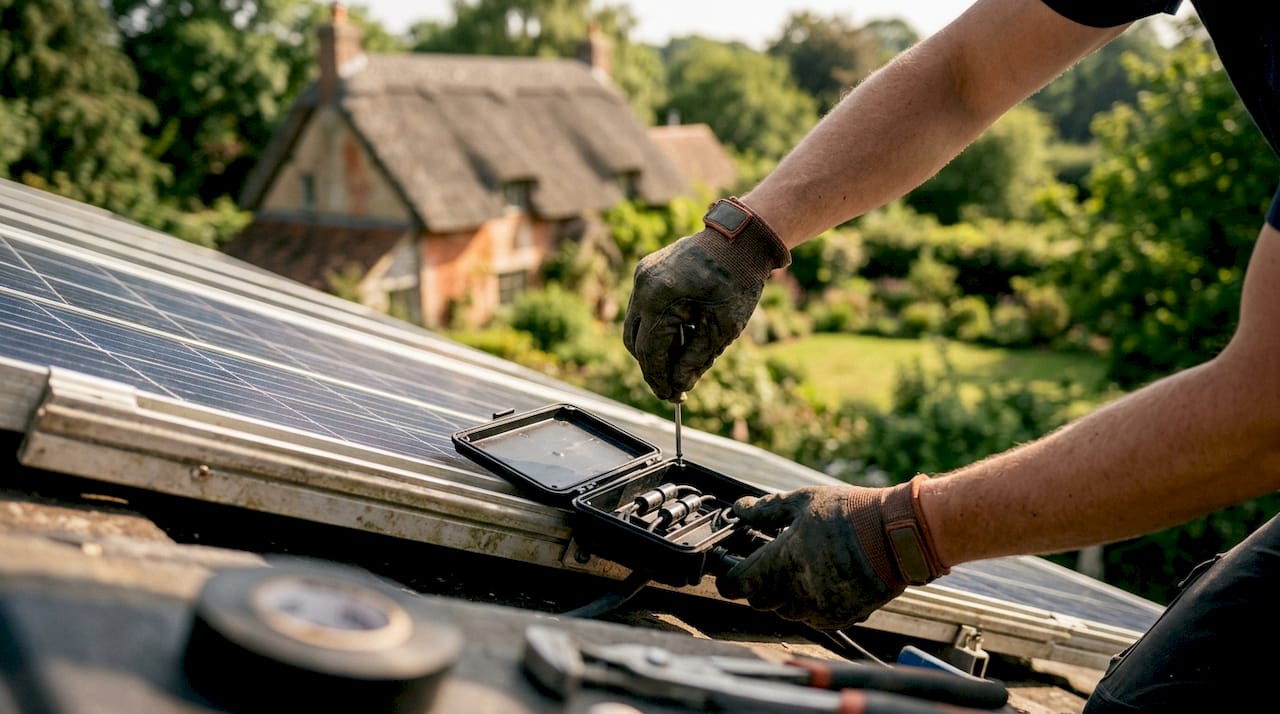
Half-cell modules effectively double the cell count because each full cell is cut in two, so the diode count scales accordingly while maintaining the 20–24 cells-per-diode guideline.
When inspecting a module physically:
- The junction box is on the rear centre or rear edge of the panel
- Cable glands where the output leads exit are the most common point of moisture ingress
- Discolouration or warping of the junction box lid suggests heat stress, possibly from a diode that has been conducting heavily or has failed
- Most junction boxes are sealed at the factory; do not open them without isolating the array first
What diode types are used as bypass diodes?
Two main semiconductor families appear in module junction boxes. SinoVoltaics documents both clearly:
- PN junction diodes: forward voltage drop of approximately 0.7V. Cheaper to manufacture, but the higher forward drop means more heat is generated each time the diode conducts. In a hot junction box on a summer roof, that thermal load matters.
- Schottky diodes: forward voltage drop of approximately 0.4V. The lower drop reduces conduction losses and keeps the junction cooler, which is why most quality modules use Schottky types. The trade-off is a slightly higher leakage current in reverse, though this is negligible in practice for PV applications.
The thermal design of the junction box matters as much as the diode choice. A poorly ventilated or poorly potted box traps heat around the diode, shortening its service life regardless of type. SolarQuotes notes that diode quality and junction-box thermal design vary considerably between manufacturers, which is one reason module quality is not simply a function of cell efficiency.
When specifying modules, check the datasheet for diode type and maximum operating temperature rating. A Schottky diode rated to 150°C in a well-sealed enclosure with a high IP rating is a meaningfully better specification than an unspecified diode in a less protected enclosure.
How do bypass diodes differ from blocking diodes?
They are often confused, but they serve opposite purposes and are wired differently.
- Bypass diodes are wired anti-parallel (shunt) across a sub-string of cells. They conduct when the sub-string is reverse-biased, protecting cells from hot-spot damage. Polarity: cathode toward the positive terminal of the sub-string.
- Blocking diodes are wired in series with a string or panel. They prevent reverse current flowing back into a string from a battery or from parallel strings that are generating more power. Polarity: anode toward the panel positive output.
- Bypass diodes are a standard feature of grid-tied crystalline modules. Blocking diodes are more common in off-grid and battery systems, where series and parallel wiring creates conditions for reverse current that grid-tied string inverters do not typically face.
- When checking wiring, a bypass diode will show continuity in one direction when measured across the sub-string terminals inside the junction box. A blocking diode will show continuity in one direction when measured in series along the string cable.
The practical takeaway: if you are troubleshooting a grid-tied rooftop system, you are almost certainly dealing with bypass diodes. Blocking diodes appear in off-grid solar and battery systems and older standalone installations.
How do bypass diodes affect your system’s output under shading?
The direct answer is that diodes protect the panel but reduce available voltage and power from the module when they activate. The protection is worth it. The production loss is real and worth understanding.
Consider a standard 60-cell module with three sub-strings and three bypass diodes. Under full sun it might produce 400W at 40V. If a chimney shadow falls across one sub-string:
- The bypass diode for that sub-string conducts.
- The module’s output voltage drops by roughly one-third (the contribution of the bypassed sub-string), to approximately 27V.
- Output power falls proportionally, to roughly 265W from that module alone.
- The remaining two sub-strings continue generating normally.
At array level, the picture gets more complicated. PV Education’s shading documentation shows how shading on one string can reduce production across parallel strings, and how an MPPT inverter may settle on a compromise operating point that does not represent the true maximum for either string. The result can be a larger production loss than the shaded area alone would suggest.
This is why shading management matters more than diode count. Diodes limit the damage; they do not eliminate it. For UK domestic roofs where chimney stacks, dormers, or neighbouring trees create partial shading, understanding how shading affects energy output is the first step toward deciding whether panel repositioning, microinverters, or DC optimisers are worth the investment.
Pro Tip: Module-level power electronics (microinverters or DC optimisers) each perform their own MPPT per panel, which eliminates the multiple-peak problem entirely. For roofs with unavoidable partial shading, they are worth costing in at the design stage.
What happens when a bypass diode fails?
Diodes fail in two distinct modes, and each has a different signature. SolarQuotes notes that both modes are field-replaceable, but each needs a different diagnostic approach.
Open-circuit failure means the diode no longer conducts even when it should. The sub-string loses its protection. Under shading, the affected cells are driven into reverse bias with no clamping, and hot-spot heating can develop rapidly. The panel may appear to be generating normally in full sun, making this mode particularly dangerous.
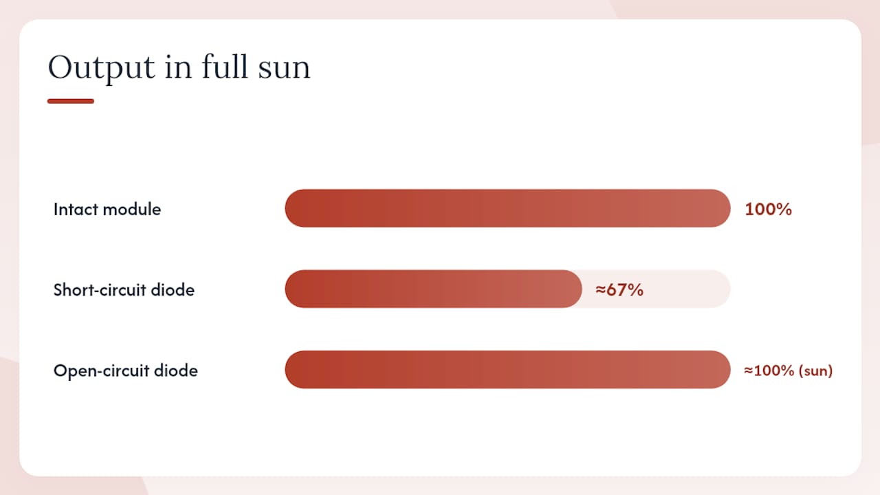
Short-circuit failure means the diode conducts permanently, even in full sun. The sub-string it protects is permanently bypassed. The module produces roughly two-thirds of its rated output (for a 3-diode module) regardless of irradiance. This is the more common failure mode in the field.
Symptoms to watch for:
- A persistent, unexplained drop in output from one string that does not recover when the sky clears
- One module running noticeably cooler than its neighbours on a thermal image (the bypassed sub-string generates no heat because it carries no current)
- Unusual warmth at the junction box itself, particularly around the diode potting area
- A module’s open-circuit voltage reading roughly two-thirds of its rated Voc when tested in isolation
A diode stuck short can be hard to detect without thermal imaging or module-level IV testing, because the panel visually appears intact while a full sub-string has been permanently bypassed. (SolarQuotes)
Hot-spot risk from an open-circuit diode is the more urgent safety concern. Sustained reverse-bias heating can reach temperatures sufficient to crack cell glass, degrade the backsheet, or in severe cases contribute to fire risk. If you suspect a failed diode and the panel shows any signs of physical damage or discolouration, isolate the array and contact a qualified installer before the next sunny day.
How to inspect and test bypass diodes safely
A homeowner can carry out a basic visual check safely. Anything involving opening the junction box, measuring live voltages, or working on the roof requires a qualified electrician.
Basic homeowner checklist (array isolated or at night):
- Visual inspection from ground level. Use binoculars if needed. Look for discolouration, bubbling, or dark patches on the rear of panels visible from the roof edge or loft hatch.
- Junction box check (from the roof, array isolated). Look for cracked lids, melted cable glands, or brown staining around the box. Do not open the box.
- Inverter monitoring review. Log into your inverter’s monitoring portal and compare string voltages and currents against the system’s baseline. A persistent low-voltage string is the clearest software-level indicator.
Installer-level testing steps:
- Isolate the array at the DC isolator and inverter. Confirm zero voltage with a calibrated multimeter before touching any connections.
- Open-circuit voltage test per module. Disconnect each module and measure Voc in direct sunlight. A reading roughly one-third below rated Voc (for a 3-diode module) suggests one sub-string is permanently bypassed.
- Diode forward-drop test. With the module disconnected and in darkness (or covered), use a multimeter in diode-test mode across each diode’s terminals inside the junction box. A healthy Schottky diode reads approximately 0.3–0.5V forward drop; a shorted diode reads near 0V; an open diode reads OL (overload/no reading).
- String current test. Use a DC clamp meter on each string cable under full sun. A string with a shorted diode will show lower current than its neighbours.
- Thermal imaging. A FLIR or similar thermal camera used during peak generation hours is the fastest diagnostic. A module with a shorted bypass diode shows a cold sub-string; a module with an open diode under shading shows a hot cell cluster.
Safety precautions for UK installations:
- DC isolators must be switched off and locked before opening any junction box
- PV arrays can remain live even with the inverter off; treat all DC cables as live until confirmed otherwise
- Work on roofs requires appropriate fall-arrest equipment; do not attempt roof-level testing without proper access equipment
- Live electrical work on PV systems must be carried out by a qualified electrician registered with a competent-person scheme such as NAPIT or NICEIC
For fault-finding guidance specific to Hampshire systems, the solar system fault-finding guide covers the diagnostic workflow in more detail.
Pro Tip: When bench-testing a removed diode, always test in both directions. A diode that reads correct forward drop but also shows partial conductivity in reverse is degraded and should be replaced even if it has not fully failed.
What installers should check when specifying modules
Bypass diode quality is rarely the headline figure on a module datasheet, but it directly affects long-term reliability. When selecting modules or surveying a site:
- Current rating: the bypass diode must be rated to handle the module’s short-circuit current (Isc) continuously. Check the diode’s rated forward current against the module’s Isc on the datasheet.
- Forward voltage: Schottky types (~0.4V) are preferable to standard PN types (~0.7V) for lower thermal load in the junction box.
- Junction-box IP rating: IP67 is the practical minimum for UK outdoor installations. IP54 boxes are more vulnerable to moisture ingress, which accelerates diode degradation.
- Maximum operating temperature: the diode’s Tjmax should comfortably exceed the maximum junction-box temperature expected on a south-facing UK roof in summer (typically 70–85°C ambient at the box).
- Serviceability: some junction boxes are fully potted and require the entire box to be replaced if a diode fails. Others allow individual diode replacement. The latter is significantly cheaper to repair in the field.
- Datasheet location: diode specifications appear in the module’s electrical characteristics table or in a separate junction-box specification sheet. Look for “bypass diode type”, “bypass diode rating”, and “junction box IP class”.
Installer questions to ask at procurement:
- Is the junction box field-serviceable or fully potted?
- What diode type and rating is used?
- Does the manufacturer’s warranty cover diode failure separately from cell degradation?
Pro Tip: On site surveys, note any roof features that will cast regular shadows on specific module positions. Modules in those positions will have their bypass diodes activating frequently, so junction-box quality and diode rating matter more there than on a clean, unshaded roof.
What UK homeowners should do next
Bypass diodes are a safety-critical component that most homeowners never need to think about until something goes wrong. Keeping them in good condition is straightforward:
- Check your inverter monitoring monthly. A persistent string voltage or current drop is the earliest warning sign.
- After any severe weather, do a visual check of junction boxes from the roof edge or via a loft hatch if accessible.
- Keep a record of your module serial numbers, installation date, and any baseline performance readings. This information speeds up diagnosis considerably when you call an installer.
- If you notice physical damage to a junction box, discolouration on the rear of a panel, or a persistent output drop, isolate the system and call a qualified electrician. Do not attempt to open junction boxes yourself.
- For a broader view of what affects your system’s output, the solar panel output factors checklist covers the full picture beyond diode health.
An installer’s perspective on bypass diode faults in the field
The calls that come in about bypass diode problems rarely start with “I think my bypass diode has failed.” They start with “my system seems to be generating less than it used to” or “my monitoring shows one string is always lower than the other.” That gap between symptom and cause is where most of the diagnostic work happens.
In practice, the shorted diode is the failure mode we see most often on UK domestic roofs. A panel that has been partially shaded by a chimney stack for several years will have had one bypass diode conducting regularly through every winter morning. That thermal cycling accumulates. When the diode eventually shorts, the homeowner notices a roughly one-third drop in output from that module, but because the rest of the system keeps running, it can go unnoticed for months without active monitoring.
UK domestic roofs present a particular challenge because the shading patterns are rarely clean. A chimney that casts a shadow on the bottom row of panels at 9am in December may cast no shadow at all from April to September. That means a diode might cycle between conducting and not conducting hundreds of times per year, which is a meaningful stress on a component that was designed to conduct occasionally, not routinely.
The repair workflow is usually straightforward once the fault is confirmed with thermal imaging. If the junction box is field-serviceable, a diode replacement takes under an hour on the roof. If the box is fully potted, the whole junction box needs replacing, which adds cost but is still a minor job compared to replacing the module. The key is catching it before the open-circuit failure mode develops, because that is when the hot-spot risk becomes a genuine concern.
Smarthometechnical: solar inspection and junction-box repair in Dorset, Hampshire, and Devon
A shorted or open bypass diode is one of the more straightforward faults on a solar system, but confirming it safely requires thermal imaging, DC isolation, and the right test equipment. Smarthometechnical carries out junction-box inspections, thermal diagnosis, and diode replacement as part of a full solar service across Dorset, Hampshire, and Devon.

All live electrical work is carried out by qualified engineers registered with a competent-person scheme, in line with UK wiring regulations. If you have noticed a persistent drop in string output, unusual warmth at the rear of a panel, or any physical damage to a junction box, the practical next step is a site survey. You can request one via the solar installations page, or if you already know the fault is junction-box specific, the junction-box repair guide for Dorset explains what the repair process involves and what information to have ready when you call.
Sources
The sources below underpin this guide. They range from academic to practical, and each serves a different purpose:
- A comprehensive review on bypass diode application on photovoltaic modules – MDPI
- Technical note: bypass diode effect in shaded conditions – SolarEdge
- Hot spot and submodules – PVsyst documentation
- Why your solar panels need bypass diodes – SolarQuotes
- Bypass diodes – Electronics Tutorials
- How do bypass diodes in PV modules work? – SinoVoltaics
Recommended
- Best solar diverters for Dorset households: 2026 guide – Smart Home Technical Ltd
- Solar panel aerial interference Dorset: what you need to know – Smart Home Technical Ltd
- The role of solar panels in homes and businesses – Smart Home Technical Ltd
- Why solar panels need surge protection: UK homeowner guide – Smart Home Technical Ltd
