
The most common roof structure solar challenges are insufficient load capacity at rafter attachment points, waterproofing failures around roof penetrations, shading and soiling losses, and wind uplift from poorly designed mountings. The single best first action is to commission a site-specific structural and roof condition survey with a named Engineer of Record (EOR) before any panels are ordered.
Three things to do before you sign anything:
- Request a structural survey with EOR sign-off that checks point loads at every attachment, not just average roof area loads.
- Insist on a 3D shade and obstruction model covering the full annual sun arc, not a single midday snapshot.
- Confirm the waterproofing strategy in writing: penetrative fixings with correct flashing detail, or a ballasted system for flat roofs.
Third-party EOR involvement demonstrably reduces design defects, and the largest structural risks consistently arise where no design professional was retained. Ask for MCS or NICEIC accreditation proof, building regulations compliance, a commissioning record, and a Permission to Operate (PTO) confirmation before the final invoice is paid.
Table of Contents
- 1. What are the main structural risks when mounting solar on a roof?
- 2. How does your roof type change the mounting approach?
- 3. Roof-driven performance problems: shading, soiling, hot spots and birds
- 4. How roof penetrations cause leaks and what good installers do differently
- 5. When do you need a structural engineer, and what does their survey cover?
- 6. Obstructions, clearances and fire-safety access on pitched roofs
- 7. Flat-roof specific risks: ponding, membrane damage and ballasted systems
- 8. Installer errors, compliance and electrical safety
- 9. Pre-install checklist: surveys and questions to ask every installer
- 10. Maintenance, monitoring and common fixes after installation
- 11. Typical costs and timescales for surveys and remedial work in the UK
- 12. Our findings and best-practice recommendations
- Key takeaways
- What a site walk actually reveals
- Smarthometechnical: professional solar installation in Dorset, Hampshire and Devon
- Useful sources and further reading
1. What are the main structural risks when mounting solar on a roof?
Structural failure in rooftop solar rarely announces itself dramatically. More often it shows up as a slow sag, a cracked rafter, or a panel that shifts in a winter storm. The underlying causes are predictable and preventable.
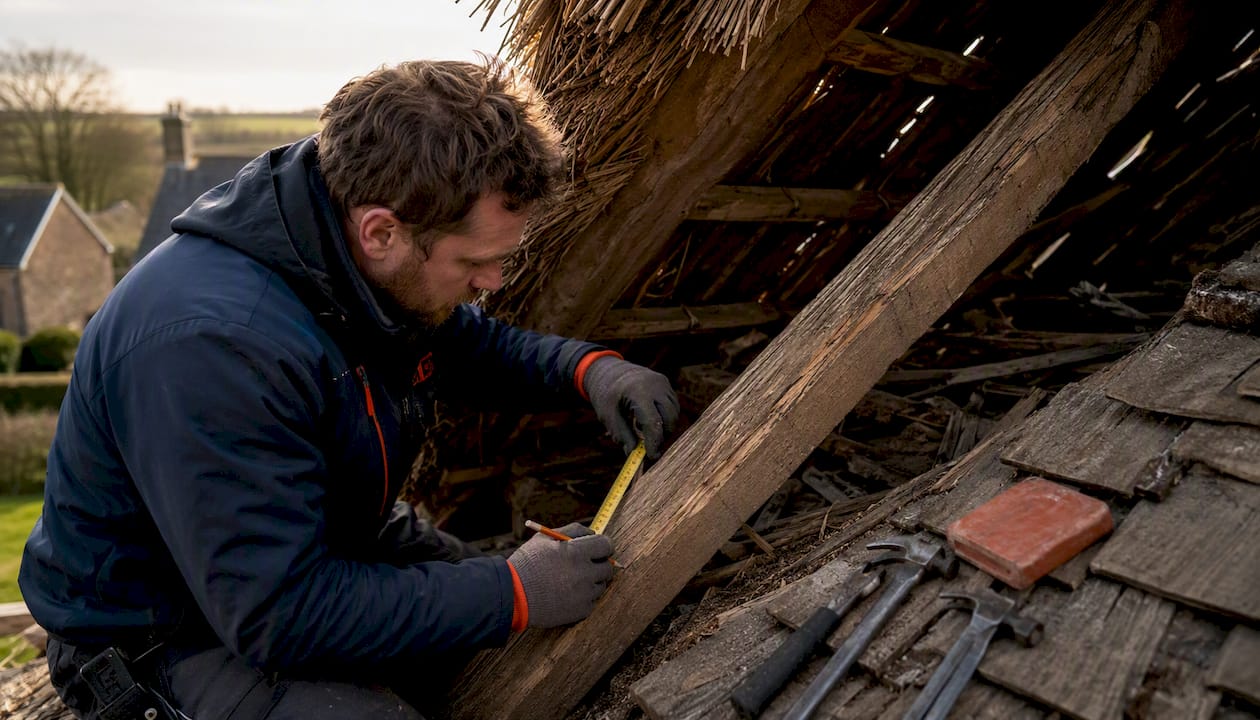
Insufficient load capacity and concentrated point loads are the most cited structural problem. A roof that passes a uniform load check can still fail at individual rafter attachment points because solar mounting hardware concentrates weight onto a small area. A proper structural check must verify capacity at the exact attachment points rather than relying on area averages. This distinction trips up many standard building control submissions.
Rot, age and existing tile layers change the picture entirely. A Victorian terrace with original rafters and two layers of old tiles may carry far less than its nominal load rating suggests. Wet rot in rafter ends is invisible from above and only shows up during a proper attic inspection.
Wind uplift is underestimated on exposed sites. Inadequate attachment spacing and insufficient fastener embedment depth are the two most common causes of panel loss during storms. The attachment design must account for local wind exposure category, not just a national average.
- Roof trusses are particularly vulnerable: drilling or cutting truss chords without certified structural engineering oversight can compromise the entire roof structure. Correct practice is to use blocking between trusses and never modify chord members.
- Missing a continuous load path from panel clamp to foundation is one of the most common reasons permits stall on structural review.
- Older roofs with complex or non-standard truss geometry need member-by-member capacity checks, not a generic calculation.
Pro Tip: Ask your installer to confirm in writing whether the structural check covers point loads at each attachment or only the roof’s general dead and live load capacity. If they cannot answer clearly, request an independent structural engineer.
2. How does your roof type change the mounting approach?
Pitched and flat roofs require fundamentally different mounting strategies, and the material on top of each adds another layer of complexity. Getting this wrong is one of the most common solar installation issues in the UK.
Pitched roofs almost always use penetrative mechanical attachments: hooks, standoffs or rail feet bolted through the tile or slate into the rafter below, then sealed with purpose-made flashing. The specific approach depends on the material.
- Clay and concrete tiles use tile-specific hooks that slot under the tile without breaking it, or replacement tile solutions where a standard tile is swapped for a mounting tile. Breakage risk is real during installation if the crew lacks experience with the tile profile.
- Natural slate is more fragile and requires specialist slate hooks; standard tile hooks will crack it. Replacement slate solutions exist but add cost.
- Metal roofs and standing seams often allow non-penetrative clamps that grip the seam profile, avoiding any membrane breach. Always verify manufacturer compatibility and check that the clamp design has been wind-load tested for your exposure zone.
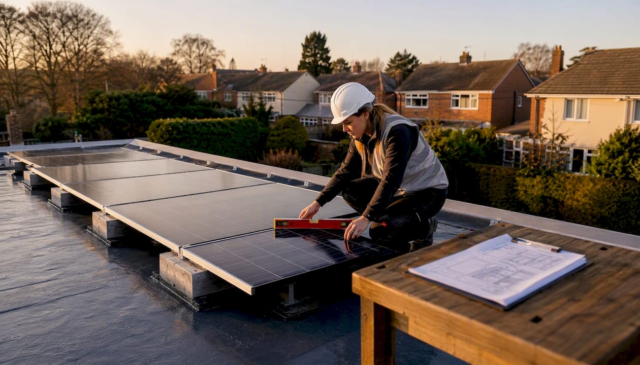
Flat roofs split into two approaches: ballasted systems that sit on the membrane weighted by concrete blocks or pavers, and penetrative fixings that anchor through the membrane into the deck below. Ballasted systems preserve the membrane but add significant dead load, which requires its own structural check. Penetrative fixings carry waterproofing risk if not detailed correctly.
| Roof type | Typical mounting approach | Key risk | Homeowner action |
|---|---|---|---|
| Pitched tile (clay/concrete) | Tile hook or replacement tile with rail | Tile breakage; flashing failure | Request tile-specific hook spec and flashing detail |
| Natural slate | Specialist slate hook | Cracking during installation | Confirm installer has slate experience |
| Metal/standing seam | Non-penetrative seam clamp | Wind uplift if clamp not rated | Check manufacturer wind-load certification |
| Flat (membrane) | Ballasted frame or membrane-penetrating anchor | Dead load increase; membrane puncture | Require structural check and membrane-safe spec |
| Flat (concrete deck) | Penetrative anchor with waterproofing detail | Leak if sealant fails | Insist on full waterproofing detail in permit package |
3. Roof-driven performance problems: shading, soiling, hot spots and birds
A structurally sound installation can still underperform badly if the roof’s geometry, surroundings, or maintenance habits are not accounted for at design stage. These are the performance-side challenges of solar roofs that often go unaddressed until the first annual yield report disappoints.
Shading is a year-round problem, not a midday one. The sun’s arc changes dramatically between June and December in the UK, and a chimney that casts no shadow at noon in July can shade two panels for three hours on a December morning. Hourly modelling across the full year is the only way to catch this. Solar 3D site models store roof geometry, obstructions and tilt angle so that shading and yield forecasts match installed performance far more reliably than a 2D sketch. Manual on-site verification of rafters and attic routing still remains necessary alongside any digital model. For a deeper look at how shading affects output, the role of solar panel shading is worth reading before you finalise a layout.
Soiling and debris accumulate faster on low-pitch roofs and in areas with tree cover or bird activity. Localised soiling on one panel creates a hotspot: the shaded cells are forced to dissipate energy as heat rather than generate it, which degrades the cell over time. Bird nesting under panels compounds this by blocking airflow and depositing acidic droppings.
- Fit bird guards (mesh skirting around the array perimeter) at installation, not as an afterthought.
- Micro-inverters or DC optimisers limit the string-level impact of partial shading: one dirty panel does not drag down the whole string.
- Panel spacing of at least 20mm at the bottom edge helps with drainage and reduces debris accumulation.
Hot spots and bypass diodes are the electrical consequence of partial shade on a string-wired array. When one cell is shaded, its bypass diode activates to route current around it, but the shaded cell still heats up. Repeated hotspot cycling shortens panel life. Layout matters: avoid placing panels where a chimney or dormer will shade even a corner of a module for extended periods.
When shading is unavoidable on a particular roof face, a ground-mount or an alternate roof face is often the better answer. Rooftop obstructions such as chimneys, vents and HVAC units reduce usable solar area, and panels placed outside formal setback zones can still suffer yield loss from shade arcs even when they technically comply with clearance rules.
4. How roof penetrations cause leaks and what good installers do differently
A large portion of residential solar callbacks relate to preventable roof leaks caused by improper flashing or sealants at roof penetration points. The frustrating part is that these leaks rarely appear immediately. Water tracks along rafters and only shows up as a ceiling stain months later, by which point the insulation is saturated and the rafter end may have started to rot.
The failure modes are consistent: sealant applied without proper flashing, standoffs seated on cracked or missing mortar, and membrane punctures on flat roofs sealed with incompatible products that degrade within two or three years.
Best practice checklist for penetrations:
- Use purpose-made flashing kits matched to the tile or slate profile, not generic lead or silicone alone.
- Seal fasteners with EPDM-backed washers and a compatible sealant rated for outdoor UV exposure.
- On flat roofs, use membrane-safe standoffs or, where possible, a fully ballasted system to avoid penetrations entirely. Understanding how to waterproof flat roofs properly is essential before any fixing goes through the membrane.
- Require an explicit waterproofing detail drawing in the permit package, not just a verbal assurance.
- If the roof covering is more than 15 years old or showing signs of wear, consider re-covering before installation. A 25-year panel array on a 5-year-old membrane is a sensible match; the same array on a membrane due for replacement in three years is not.
Before any work begins, reviewing essential pre-installation roof considerations can help you ask the right questions about flashing, drainage and material compatibility.
Pro Tip: Ask your installer to provide a named waterproofing product specification for every penetration point, and confirm it is compatible with your existing roof membrane. A good installer will have this in their standard permit package; one who cannot produce it is a warning sign.
5. When do you need a structural engineer, and what does their survey cover?
Not every solar installation requires a chartered structural engineer, but many more do than installers typically acknowledge. The threshold is lower than most homeowners expect.
A professional structural survey for rooftop solar covers:
- Document review: existing planning drawings, building control records, and any previous structural reports.
- Site inspection: attic access to inspect rafter or truss condition, check for rot, measure member sizes, and identify any previous modifications.
- Member-by-member capacity checks: calculating whether each rafter or truss can carry the additional dead load of panels, rails and fixings at the specific attachment points proposed.
- Point-load verification: confirming that concentrated loads at each standoff do not exceed the rafter’s capacity, even where the overall roof area load is acceptable.
- Load path trace: following the load from panel clamp through rail, standoff, rafter, wall plate and down to foundation to confirm continuity.
- Permit-ready calculations: stamped structural letter, attachment detail drawings and load calculations formatted for building control submission.
A rooftop structural assessment should check dead, live, wind, snow and seismic load combinations and verify continuous load paths from panel clamp to foundation. Many permits stall on structural review when these elements are incomplete.
When is a chartered structural engineer or EOR mandatory? Older roofs (pre-1960 construction), non-standard or modified trusses, high-wind exposure zones (coastal Dorset, Hampshire and Devon included), heavy snow loading areas, and any roof where the installer cannot confirm rafter sizes from attic access.
Always ask: who is the Engineer of Record for this installation? Require their name and professional registration number on all structural documents before work begins. Industry practitioners consistently report that the absence of a named EOR is the single biggest predictor of later structural claims and avoidable remediation.
6. Obstructions, clearances and fire-safety access on pitched roofs
Usable roof area is almost always smaller than the total roof area, and the gap between the two surprises many homeowners at the layout stage.
Rooftop obstructions such as chimneys, ventilation stacks, skylights, soil pipes, flues and existing aerials each require a clear setback. Regulations require specific clearance setbacks for firefighter access and ventilation, and panels placed outside formal setback zones can still suffer yield loss from shade arcs.
Common obstructions and their effects:
- Chimneys require setbacks on all sides and cast long shade arcs in winter. A central chimney on a south-facing roof can eliminate the most productive central panel positions.
- Ventilation stacks and soil pipes need clearance to remain accessible for maintenance and to avoid blocking airflow.
- Skylights and roof windows require setbacks for safe egress and fire access.
- Existing aerials and satellite dishes may need repositioning, which adds cost and sometimes requires a separate planning notification.
Fire and ventilation clearances affect panel placement on pitched roofs. UK fire guidance requires that firefighters can access the ridge and that ventilation paths are not blocked. In practice this means:
- A clear ridge run (typically 0.5m from the ridge on each side) must be maintained on many installations.
- Access corridors along the eave and up the rake are required on larger arrays.
- Set-back dimensions from roof edges and penetrations are specified in the installation design and must be reflected in the permit drawings.
These constraints are not negotiable and should be modelled at design stage, not discovered during building control review. For properties with aerials or other roof-mounted equipment, the solar panel aerial interference guide covers the practical implications in detail.
7. Flat-roof specific risks: ponding, membrane damage and ballasted systems
Flat roofs present a distinct set of challenges that pitched-roof guidance does not cover. The membrane is the most costly vulnerability: a single improper penetration can saturate insulation and corrode the deck beneath, so the choice between ballasted and penetrative systems carries real financial consequences.
Ponding and drainage are the starting point. A flat roof that drains well before installation may pond after panels are fitted, because panel rows change where water flows and can block existing outlets. Poor drainage accelerates membrane degradation and, in winter, adds ice load that was not in the original structural calculation.
Ballasted systems avoid membrane penetrations by using the weight of concrete blocks or pavers to hold the array in place. The trade-off is dead load: a ballasted system adds significantly more weight per square metre than a penetrative system, and that load is concentrated under the frame feet rather than spread uniformly. A structural engineer must verify that the deck and supporting structure can carry this concentrated load, not just the average load per square metre.
- Ballast calculations must account for wind uplift at the array perimeter, which can require additional ballast at edges and corners.
- Frame feet must sit on load-spreading pads to avoid point loads on the membrane surface.
- Drainage paths between and beneath panel rows must be maintained and checked annually.
Membrane penetration risks are significant even with quality products. Incompatible sealants, UV degradation, and thermal cycling cause failures that are difficult to locate and expensive to repair once insulation is saturated.
Pro Tip: Before any flat-roof installation, commission a drainage survey and confirm that panel rows will not redirect water towards outlets or parapet walls. Raised tilt frames (typically 10° or more) reduce ponding beneath panels and make inspection access easier.
8. Installer errors, compliance and electrical safety
Some PV fires are linked directly to installer error, and a large proportion of residential solar callbacks trace back to preventable mistakes made during installation. The electrical side of a solar installation is regulated, and the consequences of getting it wrong range from a failed inspection to a house fire.
Common installer errors:
- Poor DC wiring: undersized cables, inadequate UV protection on roof-run conduit, and connectors that are not fully seated.
- Inadequate earthing: missing or incorrectly sized protective earth (PE) conductors on the array frame and mounting rails.
- Improper string sizing: too many panels in series for the inverter’s maximum input voltage, which causes inverter shutdown or damage.
- Failed commissioning: a system that is energised but never formally tested, leaving faults undetected until a monitoring alert or a physical failure.
Delays between installation and Permission to Operate are often caused by failed inspections, paperwork errors or poor electrical design. A wait beyond about two months is a red flag that something in the compliance process has gone wrong and needs investigation.
Trust-signal checklist for installers:
- MCS (Microgeneration Certification Scheme) accreditation for the installation company, not just the individual.
- NICEIC registration or equivalent for the electrical work.
- Building control sign-off and a commissioning record signed by a qualified person.
- Public liability insurance and a workmanship warranty of at least two years (ten years is standard for MCS-certified installs).
- Client references from installations of similar scale and roof type.
If problems arise after installation, the process is: collect all paperwork, contact local building control, contact the utility interconnection team for PTO queries, and escalate to industry bodies or consumer protection if necessary.
9. Pre-install checklist: surveys and questions to ask every installer
This is the checklist to use when comparing quotes. Price matters, but the documents and answers below tell you far more about whether an installation will be safe, compliant, and performing in ten years.
Documents to request before signing:
- Structural survey report with EOR name, professional registration and signature.
- Stamped attachment detail drawings showing load path from clamp to foundation.
- 3D shading model output showing annual yield estimate and shading losses by month.
- Proof of MCS accreditation and NICEIC (or equivalent) registration.
- Copy of the proposed building control notification or permitted development confirmation.
- Workmanship warranty terms and the name of the insurer backing it.
- Commissioning plan and expected PTO timeline.
Questions to ask every installer:
- Who is the Engineer of Record, and will you provide their stamped structural letter?
- How will you seal each penetration point, and what flashing product will you use?
- What is the maximum input voltage of the inverter, and how does your string design stay within it?
- What is the maintenance plan, and what does it include in year one?
- What happens if building control requests additional structural information?
Pro Tip: Tie your payment schedule to milestones: a deposit on contract signing, a stage payment on structural sign-off and permit approval, and the final payment only after commissioning records and PTO confirmation are in your hands. Never pay in full before the system is signed off.
For a broader view of the planning and permitting process, the homeowner’s guide to solar planning covers what to expect at each stage.
10. Maintenance, monitoring and common fixes after installation
A solar installation is not a fit-and-forget asset. The roof interface, the electrical connections, and the mounting hardware all need periodic attention to stay safe and productive.
Routine maintenance schedule:
- Quarterly: visual inspection from ground level for obvious debris, bird nesting, or displaced tiles around the array perimeter.
- Annually: close inspection of flashing and sealants at all penetration points; check for cracked or lifted tiles adjacent to mounting hooks; inspect bird guard mesh for gaps; clear any debris from drainage paths on flat roofs.
- Every 3–5 years: professional inspection of mounting hardware torque, earthing continuity, and DC connector condition; thermal imaging of the array to identify hotspots.
Monitoring is the fastest way to catch problems between physical inspections. Most modern inverters provide portal access showing daily generation, string-level output, and fault codes. A string that consistently underperforms its neighbours by more than 10–15% warrants investigation: the cause is usually shading, soiling, a failed bypass diode, or a loose connector.
Common fixes:
- Re-flashing a leaking penetration: typically a half-day job if caught early; a multi-day job if the insulation beneath has saturated.
- Replacing a broken tile adjacent to a mounting hook: straightforward but requires a roofer familiar with the tile profile.
- Re-seating a loose rail clamp or standoff: a quick fix, but one that should trigger a check of all other fixings on the same rail.
- Addressing grounding issues: requires a qualified electrician; do not attempt to modify DC earthing without one.
For electrical faults at the junction box or inverter level, the solar panel junction box repair guide covers the diagnostic steps and when to call a professional.
11. Typical costs and timescales for surveys and remedial work in the UK
Costs vary by location, roof complexity and the extent of any remediation needed. The figures below are indicative ranges for UK residential projects in 2026; actual quotes will depend on site specifics, local authority requirements and the structural engineer’s scope.
Estimated cost ranges:
- Structural survey (desktop review plus site visit): £300–£800 for a straightforward residential roof; £800–£2,000 for complex trusses, older properties or high-wind exposure zones.
- Minor reinforcement (blocking between trusses, additional noggins, rafter sister boards): £500–£2,500 depending on the number of attachment points and access difficulty.
- Major structural strengthening (significant rafter replacement, truss repair or partial re-roofing): £3,000–£15,000 or more, depending on extent. At this level, the economics of the solar installation need to be reassessed.
- Re-roofing before installation (where the existing covering is near end of life): £5,000–£20,000 for a typical semi-detached, depending on material and area.
Typical timescales:
- Structural survey turnaround: 1–2 weeks from site visit to stamped report.
- Building control permit review: 4–8 weeks for a straightforward application; longer if structural information is incomplete.
- Minor remedial works: 1–3 days on site.
- Major strengthening or re-roofing: 1–4 weeks, which delays the solar installation accordingly.
Indicative figures only. Local authority requirements, listed building status, and site-specific conditions can significantly change both costs and timescales. Always obtain at least two independent quotes for structural and remedial work.
Missing attachment load paths, incorrect wind exposure categories and missing snow drift analysis are among the most common reasons permits stall. Fixing these requires complete attachment drawings and correct exposure assessments, which adds time and cost to the programme if not addressed at design stage.
12. Our findings and best-practice recommendations
Smarthometechnical’s experience across installations in Dorset, Hampshire and Devon consistently points to the same pattern: the projects that run smoothly are the ones where structural and waterproofing questions are resolved before a single panel is ordered.
On older properties, particularly Victorian and Edwardian terraces with original rafters, a structural assessment has repeatedly identified rafter sections that were undersized for the proposed array. In several cases, adding sister boards alongside existing rafters resolved the issue at modest cost and without delaying the installation significantly. Without the assessment, those installations would have proceeded on a structurally marginal roof.
High-accuracy digital twin modelling is now considered best practice for any roof with obstructions, multiple faces, or non-standard geometry. It reduces change orders and produces permit drawings that match on-site conditions far more reliably than 2D sketches. Manual verification of rafter positions and attic routing remains necessary alongside the model.
Professional recommendations for homeowners:
- Require a stamped structural letter before installation begins, not after.
- Insist on 3D modelling for any roof with a chimney, dormer, or multiple faces.
- Tie final payment to receipt of commissioning records and PTO confirmation.
- Request a documented maintenance plan at handover, not as an afterthought.
- For new builds in Hampshire, the Hampshire new build solar options guide outlines the specific considerations that apply at planning stage.
On the contract side: use milestone-based payment schedules, confirm deposit limits in writing, and never release the final payment until all compliance documents are in hand. This single practice protects homeowners from the most common installer disputes.
Key takeaways
The single most important step before any UK rooftop solar installation is commissioning a structural survey with a named Engineer of Record, combined with a full 3D shading model and a documented waterproofing strategy.
| Point | Details |
|---|---|
| Structural survey first | Commission a site-specific survey with EOR sign-off before ordering panels; point-load checks matter more than area averages. |
| Waterproofing detail in writing | Require a named flashing product and penetration spec in the permit package; flat roofs need membrane-safe or ballasted systems. |
| 3D shading model | Annual hourly modelling catches shade arcs that a single-visit snapshot misses; use it for any roof with obstructions. |
| Verify installer credentials | Confirm MCS accreditation, NICEIC registration, public liability insurance, and a workmanship warranty before signing. |
| Smarthometechnical | Smarthometechnical coordinates structural surveys, EOR sign-off, waterproofing-safe mounting, and full commissioning for UK homeowners in Dorset, Hampshire and Devon. |
What a site walk actually reveals
The conventional wisdom in solar sales is that a roof is either suitable or it is not, and a satellite image plus a shading tool is enough to tell you which. That framing is wrong, and it costs homeowners money.
Every site walk on an older property turns up something a desktop survey misses: a rafter that has been notched by a previous plumber, a tile batten that has rotted at the eave, a chimney flashing that is already lifting. None of these show up on a satellite image. None of them are captured by a 3D model. They only appear when someone opens the loft hatch, shines a torch along the rafters, and actually looks.
The same applies to shading. A model is only as good as the geometry fed into it. A mature tree on a neighbouring property, a new dormer extension, a satellite dish repositioned since the last aerial survey: these change the shade picture in ways that a digital twin cannot know unless the site visit updates it.
What this means practically is that the survey and the model are not alternatives. They are both necessary, and the site visit must come first. A model built on accurate site measurements is a genuinely useful design tool. A model built on assumptions is an expensive way to produce a drawing that will not match what gets installed.
The other thing that site walks consistently reveal is the gap between what an installer says they will do and what the permit package actually specifies. Asking to see the waterproofing detail drawing before signing is not an unreasonable request. It is the fastest way to find out whether the installer has thought through the penetration design or is planning to improvise on the day.
Smarthometechnical: professional solar installation in Dorset, Hampshire and Devon
Structural surprises and waterproofing failures are the two most common reasons a solar installation costs more than the original quote. Smarthometechnical addresses both before a single fixing goes into the roof.

For homeowners in Dorset, Hampshire and Devon, Smarthometechnical provides the full sequence: structural survey coordination with a named EOR, 3D shading modelling, waterproofing-safe mounting specification, full MCS-accredited electrical installation, commissioning, and a documented maintenance plan at handover. The process is designed so that building control sign-off and PTO confirmation arrive before the final invoice does.
Ready to find out whether your roof is suitable and what a safe installation would cost? Book a solar survey with Smarthometechnical and get a quote that includes structural and waterproofing assessment from the start, not as a surprise addition later.
Useful sources and further reading
The following sources are worth consulting directly for permits, building control guidance and technical standards relevant to UK rooftop solar.
- MCS (Microgeneration Certification Scheme): The UK’s primary accreditation body for solar installers. Use this to verify whether your installer holds current MCS certification and to understand what the scheme requires of certified installers.
- Planning Portal (gov.uk): The starting point for understanding permitted development rights for solar panels in England and when a formal planning application is required.
- Solar Energy UK: Industry body guidance on operations and maintenance for solar PV systems; useful for understanding what a proper maintenance plan should cover.
- PVGIS (EU Joint Research Centre): Free online tool for estimating solar yield at any UK location using hourly irradiance data. Useful for cross-checking the yield estimates in an installer’s proposal.
- Smarthometechnical solar installations: Overview of Smarthometechnical’s solar installation services for homeowners and businesses in Dorset, Hampshire and Devon, including survey and commissioning options.
- How solar planning works: a homeowner’s guide: Practical guide to the UK planning and permitting process, covering permitted development, building control notifications and what to expect at each stage.
Recommended
- What is a solar energy contract? A UK homeowner’s guide – Smart Home Technical Ltd
- Why solar panels lose efficiency: a UK homeowner’s guide – Smart Home Technical Ltd
- Hampshire new build solar options: 2026 guide – Smart Home Technical Ltd
- Examples of solar water heating for UK homeowners – Smart Home Technical Ltd
