
A solar cell junction box is a sealed plastic enclosure bonded to the rear of every photovoltaic (PV) module. It houses the bypass diodes, terminal connections and output cables that allow the panel to deliver electricity safely to the rest of your system. Without it, a shaded cell could overheat and destroy itself, moisture would corrode the electrical connections, and there would be no clean interface between the panel and your string wiring.
Three things to know immediately:
- Bypass diodes inside the box protect cell substrings from reverse current and hot spots when part of the panel is shaded.
- Potting resin and an IP-rated enclosure keep moisture, dust and UV away from live connections for the life of the module.
- Output cables with MC4 connectors (or equivalent) exit the box and link the panel into your array’s string wiring.
Safety callout: DC circuits in a solar array remain live whenever there is daylight. A visual inspection from a safe distance is fine for any homeowner. Opening the box, soldering connections or rewiring anything inside must be left to a qualified electrician or MCS-certified installer. Never work on live DC circuits.
Key takeaways
A solar cell junction box is the sealed enclosure on the rear of every PV module that houses bypass diodes, terminal connections and output cables, and its condition directly determines whether your array performs safely for 25 years or fails prematurely.
| Point | Details |
|---|---|
| Definition and location | A sealed enclosure on the module rear housing bypass diodes, terminals and output cables. |
| Critical specs to check | IP rating (IP65 minimum for UK roofs), max system voltage, current rating and cable cross-section. |
| Top inspection signs of failure | Scorch marks, discoloured potting, cracked cable sheaths or corroded MC4 connectors. |
| Safety rule | Never work on live DC circuits; visual inspection is safe but opening or rewiring requires a qualified installer. |
| Maintenance and replacement | Annual visual check, electrical inspection every 3–5 years; replace the module if ingress is extensive or the panel is ageing. |
| Smarthometechnical | Provides MCS-certified inspection, junction-box replacement and fault-finding across Dorset, Hampshire and Devon. |
Table of Contents
- What is inside a solar cell junction box?
- What does a solar junction box actually do?
- How are junction boxes classified?
- Key specifications to check on a datasheet
- Where does the junction box sit and how does it connect to your array?
- How to inspect a junction box safely, and when to call a professional
- Common faults and how to diagnose them
- How long does a junction box last, and when should you replace it?
- Why junction-box quality matters more than most installers admit
- Professional junction box inspection and repair across Dorset, Hampshire and Devon
- Sources
What is inside a solar cell junction box?
As TE Connectivity and industry sources confirm, the junction box is a critical but frequently overlooked panel component. Open one up and you will find a compact assembly of five main parts.
- Bypass diodes (usually Schottky type): Typically three per module, one per cell substring. Schottky diodes are favoured for their low forward-voltage drop and fast switching. Failure mode: overheating under sustained shading causes thermal runaway, which can melt the potting and scorch the enclosure.
- Terminal blocks or solder pads: The ribbon conductors from the cell strings terminate here. Failure mode: solder joint corrosion from moisture ingress reduces conductivity and eventually opens the circuit.
- Output lead cables: Usually 4 mm² or 6 mm² cross-linked polyethylene (XLPE) or similar UV-resistant cable, pre-attached at the factory. Failure mode: cable sheath cracking from UV degradation or mechanical abrasion exposes conductors to moisture.
- Connector housings: MC4 or compatible plug-and-socket connectors are crimped or moulded onto the lead ends. Failure mode: connector corrosion or a poorly seated mate creates resistance heating and arcing.
- Potting compound / encapsulant: A silicone or polyurethane resin fills the enclosure cavity, locking the components in place and excluding moisture. Failure mode: potting cracks from thermal cycling allow water to track to the terminals.
Field fault data confirms that these failure modes, particularly ingress and burned connections, are among the most common causes of reduced output in installed arrays. Some high-output modules now replace conventional Schottky diodes with active bypass switches or embedded electronics to reduce heat during shading events, though this remains less common in standard residential panels.
Pro Tip: If you can see discolouration, bubbling or a brown stain on the outside of the junction box, photograph it immediately. That visual evidence is exactly what an installer needs to diagnose whether the fault is a diode, a solder joint or moisture ingress before they open anything.
What does a solar junction box actually do?
The box performs three distinct jobs simultaneously, and losing any one of them degrades the whole system.
- Collects and routes substring currents. Each cell string inside the laminate terminates at a ribbon tab that connects to a terminal inside the box. The box gathers those currents and routes them to a single output cable, making the panel a single, connectable unit.
- Hosts bypass diodes for shading protection. When a substring is shaded, its cells cannot generate their normal voltage. Without a bypass diode, the rest of the panel would force current through those shaded cells in reverse, heating them to dangerous temperatures. The diode conducts instead, routing current around the shaded substring. The panel loses a fraction of its voltage but continues generating power safely. This is why shading on even a small area of a panel has a disproportionate effect on output.
- Provides environmental and electrical protection. The sealed, potted enclosure keeps moisture, insects and contaminants away from live connections. The IP rating quantifies that protection. The box also provides a degree of electrical isolation between the cell laminate and the external wiring.
Ancillary roles are growing. On some modules the junction box serves as the mounting point for a microinverter or DC power optimiser, integrating module-level electronics directly onto the panel back. In those configurations the box is considerably larger and more complex, but the core protective and routing functions remain the same.
Pro Tip: A single failed bypass diode does not always kill a panel outright. It may simply reduce output by roughly one third, which a basic visual inspection will miss entirely. If one panel in your string is consistently underperforming, a diode fault is the first thing a qualified installer should check.
How are junction boxes classified?
Understanding the classification axes helps you read a datasheet and judge quality at a glance.
Module-mounted vs field junction box. A module junction box is factory-sealed onto the panel laminate and contains diodes and output cables. A field junction box is a standalone enclosure used elsewhere in the array for cable splices, string combiner connections or protective devices. The two types are distinct in construction and purpose, though both carry IP ratings.
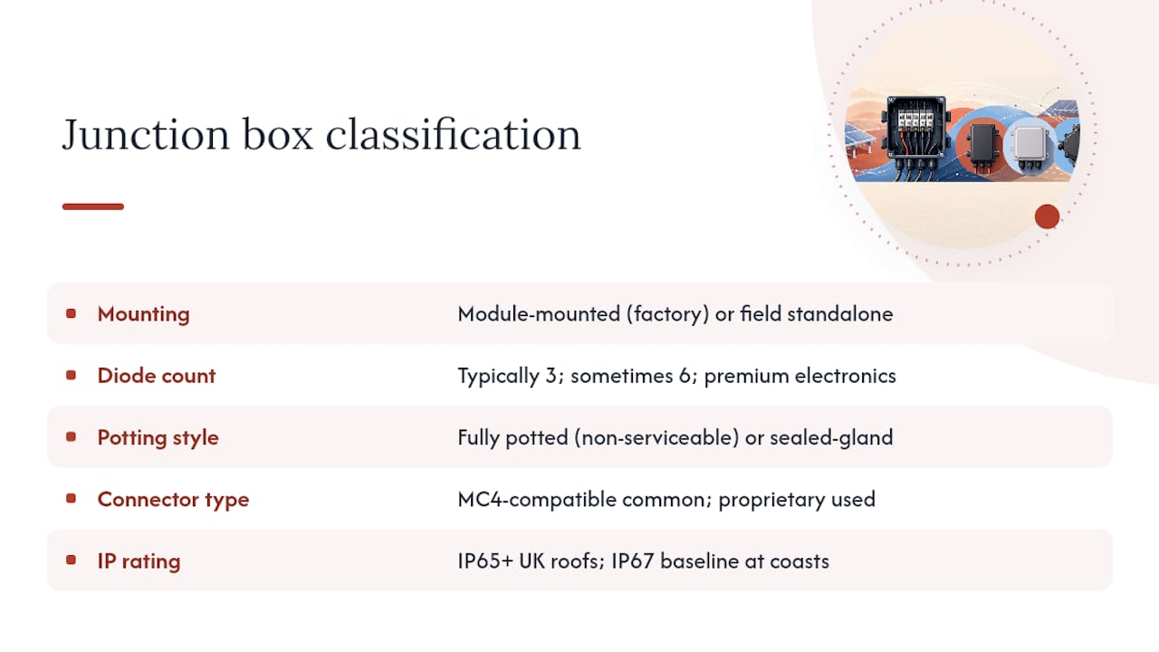
Diode count and electronics. Standard residential panels use three bypass diodes. Higher-cell-count or bifacial modules may use six. Premium designs integrate active electronics rather than passive diodes.
Potting style. Fully potted boxes are filled with resin at the factory and are essentially non-serviceable in the field. Sealed-gland designs use a removable lid and cable glands, making inspection and limited repair possible, though re-sealing must be done correctly to maintain the IP rating.
Connector type and cable. Most modern panels ship with pre-attached MC4-compatible cables. Some budget panels use proprietary connectors, which complicates replacement and can create compatibility issues in mixed-brand arrays.
The table below shows how IP ratings map to typical installation environments.
IP ratings at or above IP65 are recommended for UK roof installations. Coastal sites in Dorset, Hampshire or Devon, where salt spray and driving rain are routine, warrant IP67 as a baseline.
Key specifications to check on a datasheet
When you are reviewing a module datasheet or a replacement junction box specification, these are the figures that actually matter.
- Maximum system voltage: Commonly 1000 V DC for commercial strings, 600 V DC for some residential designs. The box must be rated at or above the maximum open-circuit voltage of your string.
- Maximum continuous current rating: Typical values run to moderate current ratings suitable for most residential panels, though higher-current modules may require boxes rated to 20 A or above. This must exceed the module’s short-circuit current (Isc).
- Operating temperature range: A range of −40°C to +85°C is standard. Roof-mounted panels in full sun can see rear-surface temperatures well above ambient, so the upper limit matters.
- IP rating: As covered above, IP65 minimum for UK rooftops.
- UV and anti-ageing resistance: The enclosure plastic must resist UV degradation. Look for a UL 746C or equivalent UV-resistance rating on the datasheet.
- Cable cross-section and length: Standard output leads are 4 mm² for most residential panels; 6 mm² is used where higher current or longer runs are needed. Lead length is typically 900 mm to 1200 mm.
- Connector compatibility: Confirm MC4 compatibility or the specific connector standard used, particularly if you are replacing a box on an existing array.
- Diode ratings: Bypass diodes should be rated for the module’s Isc and the maximum reverse voltage of a substring.
| Specification | Typical example value |
|---|---|
| Max system voltage | 1000 V DC |
| Max continuous current | 20 A |
| Operating temperature | −40°C to +85°C |
| IP rating | IP65 / IP67 |
| Output cable cross-section | 4 mm² or 6 mm² |
Where does the junction box sit and how does it connect to your array?
The junction box is mounted on the rear of the panel, typically at the centre or slightly offset toward the top edge of the module back. It is the small, rectangular sealed enclosure you can see when you look at the underside of a panel on a roof. Two cables exit from it, one positive and one negative, each terminating in an MC4 connector.
The signal path from cell to inverter runs like this:
- Individual solar cells generate DC current and are connected in series substrings within the laminate.
- Ribbon conductors carry current from each substring to the terminal blocks inside the junction box.
- The bypass diodes sit across each substring terminal pair, ready to conduct if that substring is shaded.
- The output leads exit the box through sealed cable glands and terminate in MC4 connectors.
- Those MC4 connectors mate with the string wiring on the roof, connecting multiple panels in series.
- The string cable runs to a combiner box (in larger arrays) or directly to the DC input of the inverter.
A simple schematic to request from your installer or designer: cells → junction box → string cable → inverter or combiner. That single diagram clarifies where every fault in the DC circuit can originate.
How to inspect a junction box safely, and when to call a professional
Most homeowners can carry out a safe visual inspection without any tools. Anything beyond that requires a qualified electrician working to IET Wiring Regulations BS 7671 and, for warranty-safe work, an MCS-certified installer.
Visual inspection checklist (safe for homeowners):
- Look for discolouration, scorch marks or bubbling on the box exterior.
- Check for cracked or brittle potting compound visible at the cable entry points.
- Inspect the cable sheaths along their full visible length for cuts, abrasion or UV cracking.
- Look at the MC4 connectors for corrosion, dirt ingress or a poorly seated mate.
- After severe weather, check that the box has not been dislodged or that debris has not damaged the cables.
- Photograph anything unusual before calling an installer.
If the box has a removable lid (sealed-gland type):
Opening the box must only be done with the array fully isolated. That means disconnecting the inverter, waiting for DC voltage to dissipate, and confirming zero voltage with a calibrated meter before touching anything inside. Use insulated tools rated for the system voltage. Do not attempt to re-solder connections or replace diodes unless you are a qualified electrician. Incorrect re-sealing after opening is one of the most common causes of subsequent moisture ingress.
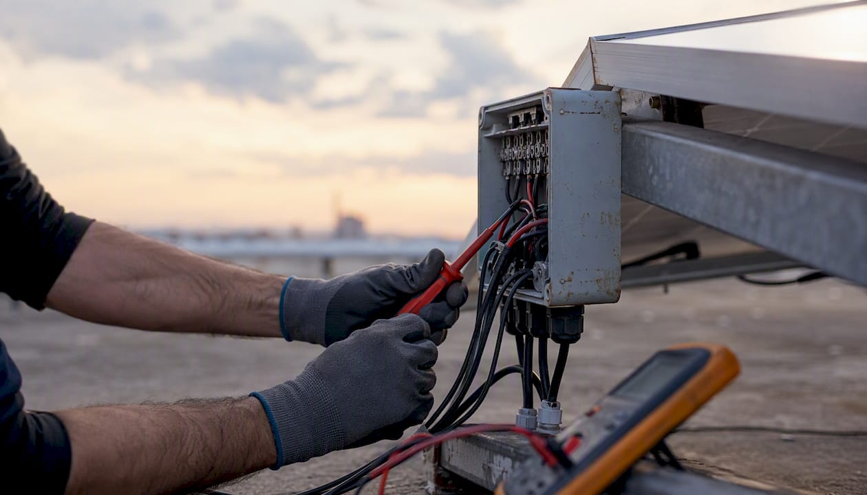
Pro Tip: Re-sealing a junction box incorrectly almost always voids the panel manufacturer’s warranty. If you open a box and then reseal it yourself, the manufacturer can legitimately decline a warranty claim on any subsequent fault. Always use a certified installer for any work that goes beyond a visual check.
Manufacturer replacement procedures, such as those demonstrated in JA Solar’s official junction box replacement instructions, involve removing potting compound and accessing solder points, steps that require trained technicians and proper equipment.
Common faults and how to diagnose them
Junction boxes are a recognised reliability concern across the industry. The most frequent faults break down into four categories.
- Moisture ingress. Water tracks through degraded cable glands or cracked potting and corrodes the terminal blocks. Symptoms: reduced output, intermittent generation, visible staining on the box exterior. Diagnostic step: visual inspection first, then an installer can measure open-circuit voltage and compare against the module’s rated Voc.
- Diode failure. A failed bypass diode either short-circuits (the substring is permanently bypassed, losing roughly one third of panel output) or open-circuits (the substring has no protection and will develop hot spots under shading). Symptoms: panel underperformance, hot spots visible on thermal imaging. Diagnostic step: IR camera scan by a qualified installer.
- Burned solder joints or terminal connections. High-resistance connections generate heat, which accelerates corrosion and can eventually cause arcing. Symptoms: scorch marks on the box, smell of burning, sharp output drop. This is a common cause of field faults and warrants immediate professional attention.
- Connector and cable faults. Corroded MC4 connectors or damaged cable sheaths create resistance heating. Symptoms: warm connectors, intermittent output, visible cable damage. See the solar panel output factors checklist for a broader view of how connector faults affect generation.
Call a professional immediately if: you see scorch marks, smell burning, notice a panel producing significantly less than its neighbours, or find any damaged cable insulation. These are not watch-and-wait situations.
Pro Tip: Repeated diode failures on the same panel are rarely a junction-box problem in isolation. They usually signal that the panel itself has a cell-level fault generating excess heat. In those cases, replacing the junction box alone is a short-term fix; the panel typically needs replacing.
For a full fault-finding procedure, the solar system fault finding guide for Hampshire covers the diagnostic steps a certified installer follows on site.
How long does a junction box last, and when should you replace it?
A well-made, properly sealed junction box should last the full life of the module. Sealed module junction boxes are designed for a long service life consistent with typical panel warranties, matching the 25-year performance warranties common on modern panels. In practice, the junction box is one of the more likely failure points because it sits on the rear of the panel exposed to thermal cycling, UV and weather.
Maintenance schedule:
- Annual visual check: Inspect cables, connectors and the box exterior. Takes five minutes and catches early signs of degradation.
- After severe weather: Check for physical damage, dislodged boxes or cable abrasion caused by debris.
- Every 3–5 years: Have a qualified installer carry out an electrical check, including connector resistance and a thermal scan if output has dropped.
Repair vs replace decision checklist:
- If moisture has reached the terminal blocks, repair is rarely cost-effective. The corrosion is usually more extensive than it appears.
- If a single diode has failed and the box is otherwise sound and dry, a qualified installer may replace the diode or the whole box.
- If the panel itself is more than 15–20 years old and showing cell degradation, replacing the module rather than repairing the junction box is usually the better investment.
- Always check whether the repair will void the remaining manufacturer warranty before proceeding.
For homeowners in Devon, the guide to extending solar panel lifespan covers the broader maintenance picture alongside junction-box care.
Why junction-box quality matters more than most installers admit
The junction box is genuinely the weak link in a PV module, not because the engineering is poor but because it sits at the intersection of three hostile forces: heat from the cells below, weather from outside and mechanical stress from the cables. Most of the time it handles all three without complaint for decades. When it fails, though, the failure mode is rarely obvious from the roof.
The pattern Smarthometechnical sees repeatedly in the field is this: a homeowner notices their generation figures have drifted down over a year or two, assumes it is normal panel degradation, and only calls when the drop becomes unmistakable. By that point, what started as a degraded cable gland has allowed enough moisture in to corrode two terminal blocks and stress a diode. A job that might have been a straightforward junction-box swap becomes a panel replacement.
The fix is not complicated. An annual visual check and a professional electrical inspection every few years catches the vast majority of junction-box faults before they cascade. The panels that reach 25 years in good health are almost always the ones that had a qualified installer look at the rear of the array occasionally, not just the inverter display.
Using an MCS-certified installer for any repair also matters for a less obvious reason: it keeps the manufacturer warranty intact. A homeowner who opens a junction box and re-seals it incorrectly has, in most manufacturers’ terms, voided the warranty on that module. The cost of a professional inspection is trivial against the cost of a panel that a manufacturer can legitimately refuse to replace.
Professional junction box inspection and repair across Dorset, Hampshire and Devon
If your panels are underperforming, you have spotted a damaged cable or connector, or you simply want a qualified eye on the rear of your array, Smarthometechnical offers inspection, diagnostic reporting and junction-box or full-module replacement across Dorset, Hampshire and Devon.

Every visit is carried out by MCS-certified engineers working to BS 7671, so any repair or replacement is warranty-safe and fully documented. The service covers visual and electrical inspection, thermal imaging where needed, junction-box replacement, full-module swap where repair is not viable, and warranty liaison with the panel manufacturer. No guesswork, no shortcuts.
Book a solar inspection or read the detailed junction box repair guide for Dorset to understand what a fault-finding visit involves before you pick up the phone.
Sources
The following references support the technical claims in this article and are worth bookmarking if you want to go deeper on specifications or standards.
- PV junction box: overlooked yet important part of the solar panel
- Solar Panel Junction Box: What It Is And Why It Matters
- Junction Box: Definition, Types & Solar Applications | Qbits Energy
- Solar Junction Boxes & Connectors Explained – Raychem RPG
- Solar Cable,MC4 Connector,Sola|Solar Panel Mounting
