
A solar energy flow diagram is a visual map showing how electricity moves through a photovoltaic (PV) system, from sunlight striking the panels through to powering your home or exporting surplus to the grid. The standard residential grid-tied flow looks like this:

Solar PV panels (DC) → inverter (DC to AC) → consumer unit → home loads or export to grid
The UK grid operates at 50 Hz, which is why every grid-tied system must convert the direct current (DC) produced by panels into alternating current (AC) before it can power appliances or feed back to the network. That conversion is the inverter’s job, and it sits at the centre of every residential flow diagram.
- Solar PV panels generate DC electricity via the photovoltaic effect
- The inverter converts DC to AC at the correct grid frequency
- AC passes through the consumer unit to serve home loads
- Surplus generation travels back through the meter and out to the grid
- A generation meter records total output for export tariff purposes
Pro Tip: When space on a diagram is tight, place the meter and AC isolator/disconnect close to the point of common coupling. Permit reviewers and DNO engineers look for these first — having them clearly labelled cuts review time noticeably.
Table of Contents
- What are the main types of solar energy diagram?
- Which components must every flow diagram show?
- How do you read and draft a permit-ready SLD?
- What UK safety and permit standards apply to solar diagrams?
- What do annotated example diagrams look like in practice?
- How long does diagram preparation take, and what drives the cost?
- What mistakes cause permit rejections, and how do you avoid them?
- Key takeaways
- Why the diagram matters more than most installers admit
- Smarthometechnical can handle your solar diagrams and installation
- Useful sources and further reading
What are the main types of solar energy diagram?
Not every diagram serves the same audience, and submitting the wrong type to a permit reviewer is one of the most common causes of delay.
| Diagram type | Primary use | Who reads it |
|---|---|---|
| Single-Line Diagram (SLD) | Building permit submission | Authority Having Jurisdiction (AHJ), building control |
| Utility interconnection diagram | DNO / DSO notification and export approval | Distribution Network Operator engineers |
| Homeowner schematic | Planning conversations, budgeting, educational overview | Homeowners, project managers |
| Battery-hybrid / off-grid diagram | Systems with battery storage or charge controllers | Installers, design engineers |
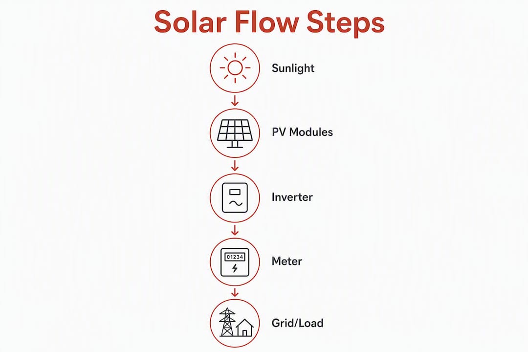
A Single-Line Diagram is the technical legal document at the heart of any permit package. It shows the full electrical path and protective devices in a simplified single-line format rather than drawing every conductor separately. A utility interconnection diagram focuses on the meter, point of common coupling, and export arrangements — the details a Distribution Network Operator needs to approve the connection.
Homeowner schematics are conceptual. They communicate the idea of how solar energy works without specifying protection device ratings or string calculations. Useful for planning conversations, but they will not pass a technical permit review on their own.
Battery-hybrid diagrams add a further layer: charge controllers, battery banks, DC busbars, and battery isolation switches all need to appear, with DC and AC sides clearly distinguished.
Which components must every flow diagram show?
Balance of System (BoS) equipment is the most overlooked area in amateur diagrams. BoS covers everything beyond the panels themselves: wiring, isolators, fuses, meters, and monitoring. Miss any of it and the diagram will fail inspection.
| Component | What to show on the diagram |
|---|---|
| PV modules | Module count, rated power, string configuration |
| Inverter | Make, model, rated output, DC input range |
| DC isolator | Location, voltage and current rating |
| AC isolator / main switch | Location relative to consumer unit |
| Fuses / overcurrent protection | Rating and type (BS standard or equivalent) |
| Earthing / protective earth (PE) | Earth conductor route and connection point |
| Generation meter | Location, meter type (smart or analogue) |
| Export / import meter | Bi-directional or separate meters |
| Monitoring system | CT clamp or gateway location |
| Cable routes and sizes | Conductor cross-section in mm², route description |
Inverter choice changes what the diagram must show. A standard string inverter means one set of DC inputs from a series string. Add power optimisers or microinverters and you need per-module labelling, individual maximum power point tracking notes, and different fault-current annotations. Panel-level electronics materially change the electrical flow, so the diagram must reflect the actual hardware.
Pro Tip: Label every string with its open-circuit voltage (Voc) and short-circuit current (Isc) directly on the diagram. Inspectors use these figures to verify that the DC isolator and fuse ratings are appropriate — if the numbers are missing, expect a revision request.
How do you read and draft a permit-ready SLD?
A clear SLD speeds permit review by giving the reviewer everything they need on one sheet. Work through this checklist in order:
- Title block — site address, installer name and certification number, drawing number, revision, and date.
- Array details — number of modules, module make and model, string configuration (modules per string × number of strings), Voc and Isc per string.
- DC side — DC cable size (mm²), DC isolator rating, surge protection device if fitted.
- Inverter — make, model, rated AC output, grid frequency (50 Hz), and anti-islanding standard (G99 or G98 as applicable).
- AC side — AC cable size, AC isolator, generation meter location.
- Consumer unit connection — dedicated circuit breaker rating, connection point in the consumer unit.
- Export / import metering — meter type and location, direction-of-flow arrows.
- Earthing — PE conductor route, earth rod or TN-S/TN-C-S connection as appropriate.
- Symbol legend — a small key for inverter, isolator, meter, CB, and earth symbols.
- Verification — cross-check string Voc against inverter maximum DC input voltage; confirm Isc against fuse ratings; attach inverter and module datasheets.
Pro Tip: Draw the flow from left to right: array on the left, grid connection on the right. Export direction arrows pointing right make the diagram immediately readable to any reviewer, regardless of their familiarity with your specific layout.
What UK safety and permit standards apply to solar diagrams?
UK solar installations must satisfy several overlapping frameworks, and the diagram is where compliance is first demonstrated.
| Standard / body | What it covers | Where it appears on the diagram |
|---|---|---|
| BS 7671 / IET Wiring Regulations | All fixed electrical wiring, protective devices, earthing | Cable sizes, CB ratings, earthing notes |
| MCS certification | Installer and product standards for grid-connected PV | Installer MCS number in the title block |
| DNO / DSO notification (G98 / G99) | Export permission and anti-islanding requirements | Inverter G98/G99 compliance note, DNO reference |
| Ofgem (Smart Export Guarantee) | Export metering and tariff eligibility | Meter type and location on diagram |
Ofgem guidance makes clear that utility-facing diagrams must show export metering and the method of interconnection. For systems up to 3.68 kW per phase, G98 notification applies; larger systems require full G99 application and engineering review. Both require the inverter’s anti-islanding compliance to be stated on the drawing.
Mark the relevant BS 7671 edition in the title block. Include the installer’s MCS certificate number and the equipment datasheets as appendices. If a Competent Person Scheme (such as NICEIC or NAPIT) notification applies, reference it on the drawing.
What do annotated example diagrams look like in practice?
Three diagram types cover the vast majority of residential projects.
-
Single-string rooftop grid-tied SLD: Eight modules in one string, string inverter, DC isolator on the roof, AC isolator at the consumer unit, generation meter, and bi-directional export meter. Copy the title block, string Voc/Isc table, and equipment schedule directly into your template. Attach the inverter and module datasheets. This is the minimum viable permit package for a straightforward residential solar installation.
-
Hybrid system with battery: The DC side splits after the inverter into a battery charge controller and battery bank. Show DC coupling point, battery isolation switch, battery management system (BMS) reference, and the AC output from the hybrid inverter. For a hybrid solar battery system, the battery’s rated capacity and maximum charge/discharge current must appear on the diagram.
-
Homeowner conceptual schematic: A simplified block diagram showing sun → panels → inverter → home → grid, with approximate kWp and estimated annual yield. No protection device ratings needed here. Use it for planning conversations and budgeting, then commission a full SLD before permit submission.
When adapting any template, keep the title block, symbol legend, and equipment schedule. Add site-specific string calculations, cable routes, and protection ratings. Attach datasheets as numbered appendices and reference them in the equipment schedule.
Pro Tip: Keep an editable symbol legend as a separate layer in your CAD or drawing file. When the inverter model changes late in the project, you update one block rather than redrawing the whole sheet.
How long does diagram preparation take, and what drives the cost?
| Stage | Approximate duration |
|---|---|
| Initial site survey | A few hours |
| Draft diagram | Several days |
| Technical review and revisions | A few days |
| Permit / building control submission | Several working days |
| DNO notification (G98) | Several weeks |
| DNO application (G99) | Several weeks |
Incomplete SLDs are the single biggest cause of delays. Missing datasheets, incorrect stringing calculations, and absent isolator ratings each trigger a revision cycle that adds days or weeks. For solar planning in the UK, getting the diagram right at first submission is worth the extra preparation time.
Cost drivers include survey complexity, the number of array strings, battery system inclusion, and whether a professional engineer sign-off is required. A templated diagram for a simple single-string system costs far less than a multi-string hybrid with G99 engineering review.
What mistakes cause permit rejections, and how do you avoid them?
Common errors that trigger rejection or revision requests:
- Omitting BoS items: no DC isolator shown, no earthing route, no monitoring reference
- Incorrect stringing: string Voc exceeds inverter maximum DC input voltage
- Cable sizes missing or unlabelled
- Export direction arrows absent or pointing the wrong way
- Inverter datasheet not attached
- MCS installer number missing from the title block
- G98/G99 compliance note absent
Best-practice checklist before submission:
- [ ] Title block complete: address, installer, MCS number, revision, date
- [ ] All BoS components shown with ratings
- [ ] String Voc and Isc calculated and labelled
- [ ] Cable sizes in mm² on every conductor
- [ ] DC and AC isolators located and rated
- [ ] Earthing route shown to BS 7671
- [ ] Export meter shown with direction arrows
- [ ] Anti-islanding note referencing G98 or G99
- [ ] Inverter and module datasheets attached as appendices
- [ ] Installer certification details included
Pro Tip: Build a permit-ready folder before you start drawing: inverter datasheet, module datasheet, MCS certificate, and signed declaration of conformity. Attach all four at first submission. Reviewers who receive a complete package on day one rarely ask for revisions.
Key takeaways
A solar energy flow diagram is a technical document that maps electricity from panels to loads or grid — accuracy in the Balance of System details and protective device ratings determines whether it passes permit review or gets returned.
| Point | Details |
|---|---|
| SLD is a legal document | Accuracy in stringing, ratings, and BoS items directly affects safety and permit approval. |
| Always show bi-directional flow | Export direction arrows and metering are required by Ofgem and DNO engineers for grid-connected systems. |
| BoS omissions cause rejections | Wiring, isolators, earthing, and monitoring must all appear with correct ratings. |
| UK standards are non-negotiable | BS 7671, MCS certification, and G98/G99 compliance notes must be referenced on every permit drawing. |
| Smarthometechnical produces permit-ready SLDs | For homeowners and businesses in Dorset, Hampshire, and Devon, Smarthometechnical handles site survey, diagram drafting, and permit submission. |
Why the diagram matters more than most installers admit
Most permit rejections are not caused by bad systems. They are caused by diagrams that do not match the system. A homeowner schematic submitted as an SLD, a string Voc that was never checked against the inverter’s maximum input, an earthing route drawn from memory rather than measured on site — these are the real culprits.
The industry tends to treat diagram preparation as a paperwork formality. It is not. The SLD is the first place an inspector looks to decide whether a system is safe. A diagram that accurately reflects the hardware, the stringing, and the protection devices is evidence that the designer understood the system before it was built. A vague sketch is evidence of the opposite.
There is also a practical point that rarely gets mentioned: a correct diagram makes fault-finding faster years after installation. When a protection device trips or an inverter throws an error, the person investigating needs to know exactly what is connected where. A permit-ready SLD is the document that answers that question.
Smarthometechnical can handle your solar diagrams and installation
Getting a permit-ready SLD right first time saves weeks of back-and-forth with building control and your DNO. Smarthometechnical provides site surveys, SLD drafting, permit submission support, and full electrical installation across Dorset, Hampshire, and Devon — so you get one team handling the technical drawings and the physical work, with no handover gaps.

Whether you need a diagram reviewed before submission or a complete solar installation from survey to sign-off, Smarthometechnical’s MCS-certified engineers cover the full process. Request a site survey or diagram review today and get your project moving without the permit delays.
Useful sources and further reading
- National Grid ESO — grid frequency, export, and system integration context for UK PV
- National Grid: how solar power works — plain-English explanation of PV and inverter roles
- Ofgem — export metering, Smart Export Guarantee, and grid interaction guidance
- ATE Central: Balance of System equipment and system design — training materials covering BoS components and flow diagram construction
- Greenlancer: guide to a solar energy diagram for installers — practical SLD guidance and permit-package advice
- SurgePV: how solar panels work — technical grounding on the photovoltaic effect and inverter requirements
- BBC Bitesize: how solar cells work — accessible explanation of DC generation and why inverters are needed
- Smarthometechnical: solar installations — local guidance and professional support for UK homeowners and businesses
- Solar Energy Management: residential solar guide — homeowner-focused overview of residential PV flow and system components
